
What Is a 4 Axis CNC Machine?
One rotary table is the whole difference between a 3 axis mill and a 4 axis mill. This page explains how that rotation is driven, which features it lets you cut in a single setup, and the part shapes where it stops helping.
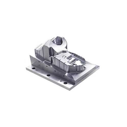
How the Fourth Axis of an Axis CNC Machine Moves
A standard 3 axis mill moves the tool along three linear directions: X, Y and Z. A 4 axis CNC machine keeps all three and adds one rotary axis. On a vertical mill that rotary axis is usually called A and turns around the X direction. Horizontal mills often use B, turning around Y.
The rotary axis is normally a servo-driven table, chuck or indexer mounted on the machine bed. The workpiece is clamped to it and the table turns to present a new face to the spindle. The controller coordinates that rotation with the linear moves, so the tool can follow a path around a cylinder instead of only across a flat surface.
The key word is coordinated. On a true 4 axis machine the rotary axis can turn while X, Y and Z are cutting. That allows helical milling, wrapped contours and continuous cuts around a shaft. Some shops run what they call 3+1: the table indexes to a new angle, locks, and then cuts with three linear axes only. That is cheaper than full simultaneous motion and covers a lot of work.
Mechanically, the fourth axis is a gearbox and a brake. A worm gear or harmonic drive multiplies servo torque and holds the table against cutting force. Backlash in that gearbox shows up directly in the part, so a worn rotary table drifts on angular features long before the linear axes do.
Indexing Versus Simultaneous Motion
Vendors use the same phrase for two different machines, so it pays to ask which one you are buying. An indexing fourth axis rotates to a set angle, stops and clamps. The cut then happens in three linear axes. This is the common setup on a vertical mill with a bolt-on rotary table.
A simultaneous fourth axis interpolates the rotary and linear axes at the same time. The controller solves a four-axis path, so the tool stays on a wrapped surface continuously. This is what you need for a cam profile, a spiral flute or a port that wraps around a bore.
The distinction matters for quoting. Indexing work is priced close to 3 axis milling because cycle times are similar. Simultaneous work needs post-processor support, longer CAM time and a machine with a rotary axis rated for continuous motion rather than clamping torque alone.
A quick test: if every rotary position in your program is followed by a clamp, the part is indexing work. If the rotary feed rate appears on the same block as X, Y or Z moves, it is simultaneous.
Which Part Shapes Suit a Fourth Axis
The fourth axis earns its cost on parts that are long relative to their diameter, or that carry features on several faces around a common centerline. Shafts with milled flats, keyways and cross holes are the classic case. So are hydraulic manifolds, valve bodies and cylindrical housings with ports at different clock positions.
Consider a shaft 300 mm long with six milled flats at 60° spacing and two cross holes. On a 3 axis mill each flat needs its own setup, and each setup adds a fixture, a dial-in and a chance of losing concentricity. On a 4 axis mill the part is clamped once in a chuck and the table indexes between flats. Setup time drops from hours to minutes, and the flats stay true to the same centerline.
Parts that are mostly flat, with all features reachable from one direction, gain little here. A plate with pockets and holes on one face will run faster on a 3 axis machine with a good vise and a tool change strategy that keeps the spindle busy.
Very complex organic surfaces are a different problem. If the tool has to tilt to reach an undercut, a fourth axis only helps when the undercut wraps around the rotary centerline. Otherwise the reach problem stays unsolved.
Setup, Fixturing and Accuracy
The fourth axis changes fixturing more than it changes cutting. A chuck or a 5C collet on the rotary table holds round stock well. Square or irregular parts need a dedicated tombstone or a custom fixture, and that fixture has to be dialed in to the rotary centerline within a few microns or every angular feature shifts.
Long parts need support at the free end. A tailstock keeps a shaft from lifting under cut, and it also keeps the part from walking in the chuck. Without it, a 300 mm shaft can deflect enough to lose tolerance on the far end, even when the machine itself is fine.
Angular accuracy is the number to watch. Linear accuracy on a well-kept mill is measured in microns, but a rotary table can carry 15 to 30 arc-seconds of positioning error, and backlash adds more. For a feature 100 mm from the centerline, 30 arc-seconds is roughly 0.015 mm of arc length. That is often the dominant error on the part.
Thermal drift matters too. A rotary table that runs continuously for hours warms up and shifts. On tight jobs we index, cut, and re-check a reference feature at intervals rather than trusting the first article all day.
Where the Fourth Axis Sits Between 3 and 5 Axis
Think of the three options as answers to different reach problems. Three linear axes reach whatever faces the spindle. A fourth axis adds rotation around one centerline, so it reaches every clock position at that radius. A fifth axis adds tilt, which reaches undercuts and steep walls that rotation alone cannot present to the tool.
Cost tracks that ladder. A 3 axis machine has the lowest hourly rate and the simplest programming. A 4 axis machine costs more per hour but removes setups. A simultaneous 5 axis machine costs the most and needs the most CAM effort, but it can machine a part in one continuous pass that would take three setups otherwise.
For most turned-and-milled parts, 4 axis is the sweet spot. The part has a dominant centerline, the features sit around it, and the tolerances are tight enough that re-fixturing is a real risk.
Go to 5 axis when the geometry has no single centerline to rotate about, or when a deep pocket needs a short, stiff tool held at an angle. Stay at 3 axis when the part is flat and the volume is high, because a dedicated fixture and fast cycle time beat flexibility.
CAM, Post-Processors and Toolpaths
Programming a 4 axis job is mostly a CAM problem. The post-processor has to output the rotary axis in the machine's own convention: which direction is positive A, where the rotary zero sits, and whether the controller wants degrees per minute or inverse feed. Get that wrong and the first run scraps the part.
Wrapped toolpaths are the workhorse. The CAM system unrolls the cylindrical surface into a flat plane, you program the cut there, and the post wraps it back onto the rotary axis. This works well for slots, flats and pockets on a diameter.
For continuous rotary cutting, feed rate needs care. The surface speed at the tool tip changes with radius, so a feed that is right at Ø100 mm is too slow near the center and too fast at the rim. Many controllers compensate; some do not. Check the machine manual before trusting a wrapped feed.
Verify with stock simulation that includes the rotary table and the chuck. Collisions between the holder and the table are the most common crash on a 4 axis machine, and they happen in the first minute of the cycle.
Choosing Between 3, 4 and 5 Axis
Match the machine to the geometry, not to the spec sheet.
| Part feature | 3 axis | 4 axis | 5 axis |
|---|---|---|---|
| Flat plate, one face | Best fit | No gain | Overkill |
| Shaft with cross holes | Two or more setups | Best fit | No gain |
| Ports at many clock angles | Slow, error prone | Best fit | Works, costs more |
| Undercut around a bore | Not reachable | Not reachable | Best fit |
| Deep pocket, short tool | Limited reach | Limited reach | Best fit |
| High-volume simple part | Best fit | Higher hourly rate | Highest hourly rate |
| Long part, tight runout | Fixture risk | Best fit with tailstock | Works, costs more |
The Short Answer
If your part has one dominant centerline and features around it, a 4 axis machine removes setups and holds concentricity better than 3 axis. If the geometry has no such centerline, or a deep pocket needs a tilted short tool, go to 5 axis instead.
Common Questions
Is a 4 axis machine the same as a 3+1 machine?
No. A 3+1 machine has a rotary table that indexes and clamps, then cuts with three linear axes. A true 4 axis machine interpolates the rotary axis with X, Y and Z at the same time.
Both are sold as four-axis machines, so ask the builder whether the rotary axis can move during a cut. The answer changes what you can program.
What angular accuracy should I expect from a rotary table?
A typical worm-gear table holds 15 to 30 arc-seconds of positioning accuracy when new, plus backlash. At a 100 mm radius that is roughly 0.007 to 0.015 mm of arc length.
This is often larger than the linear accuracy of the machine, so on angular features the rotary table sets the tolerance, not the ball screws.
Can a 4 axis machine replace a lathe with live tooling?
For small parts, sometimes. A mill-turn center with a rotary axis can turn and mill in one setup, which suits parts under about Ø100 mm.
For larger diameters or heavy stock removal, a dedicated lathe is still faster. The choice comes down to part size and how much turning the job needs.
How do I hold a square part on a fourth axis?
Use a tombstone fixture or a custom block mounted to the rotary face. Dial the fixture to the rotary centerline before the first cut.
If the part has no natural centerline, check whether a 3 axis setup with two vises is actually cheaper than building the fixture.
Does the fourth axis improve surface finish?
It can, when it lets you keep the same tool and the same setup across several faces. Fewer setups mean fewer transition marks and less mismatch at corners.
Finish still depends on the toolpath, the stepover and the rigidity of the setup. The fourth axis does not fix a chattering part.
What size parts fit a 4 axis mill?
It depends on the table. Our four-axis mills cover a Ø400 mm rotary table, and larger work can be handled on machines with up to 4,000 mm of processing length.
Weight and overhang matter as much as length. A long part with no tailstock support will deflect regardless of table size.
Send Us Your Part and We Will Tell You Which Axis Count You Need
Upload a STEP file and we will come back with a process note: axis count, fixturing, and the tolerances we can hold.
12-hour quote100% inspectionNo minimum order
More Machining Notes
We publish setup notes, tooling trials and inspection data from the factory floor.











