
What Is 3 Axis CNC Machine Geometry?
A 3 axis machine moves the cutting tool along three linear axes and keeps the part still. This page explains the mechanism, the setup limits, and the part shapes where three axes are the cheaper, faster choice.
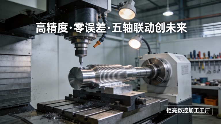
How the Three Axes Work
A 3 axis cnc machine has three linear slides. X and Y position the part or the spindle in the horizontal plane, and Z controls the depth of cut. In a vertical machining center (VMC), the part sits on a table that travels in X and Y while the spindle moves in Z. In a mill with a moving column, the tool travels instead. The geometry is the same: three straight axes, no rotation of the work.
The controller reads G-code and interpolates. A straight move is a G01 block; an arc is G02 or G03; a hole pattern is a canned cycle. Because the tool axis stays vertical, every cut comes from the same direction. Floors, walls and pockets can be reached, but a face pointing sideways cannot.
That single-direction rule sets the real boundary. A part with features on one face, or on faces a fixture can present to the spindle, is a good fit. A part with features wrapping around five sides needs either more setups or a rotary axis.
The machine does not know which side it is cutting. It only follows coordinates. So the question is never whether the machine can cut a feature, but whether the fixture can present that feature to the tool without losing position between setups.
- 1X and YHorizontal positioning of the table or the spindle head.
- 2ZVertical travel that sets depth of cut and clearances.
- 35-axis machineAdds two rotary axes so the tool can tilt relative to the part.
Vertical, Horizontal and What They Reach
Most 3 axis cnc machine tools on a shop floor are vertical. The spindle points down, the table is open on three sides, and the operator can see the cut. That layout suits plate work, housings, brackets and mold inserts where the main features sit on one face or on two parallel faces.
A horizontal machining center turns the spindle sideways. Chips fall away instead of piling in the pocket, which matters in deep pockets and in materials that smear. Horizontal machines often carry a tombstone or a pallet changer, so a second part can be loaded while the first is cutting.
The travel envelope decides what fits. A small VMC with a 500 × 500 × 450 mm envelope handles most brackets and manifold blocks. A long-bed machine with 4,000 × 400 × 150 mm travel takes extrusion profiles, rails and long plates that would not fit on a standard table.
Pick the layout from the part, not the other way round. Deep cavities with tight corners favor a horizontal spindle. Long parts favor a long X travel. Parts with features on four sides favor a rotary table on a 3-axis base, which is where 4-axis work begins.
- 1Vertical spindleBest visibility and easiest fixturing for plate and block work.
- 2Horizontal spindleChips clear the cut; good for deep pockets and pallet work.
- 3Long-bed travel4,000 mm X travel for profiles and rails.
Setup Count Is the Real Limit
A three-axis machine cuts from one tool direction at a time. If a part has features on six sides, each new side needs a new setup: unclamp, reposition, re-fixture, re-zero. Every setup adds an alignment step and an hour of indirect labor.
Datum error is the quiet cost. A vise stop that repeats within 0.02 mm is fine for a bracket and not fine for a bearing bore that must line up with a hole on the opposite face. When two features must be coaxial within 0.01 mm, a single-setup process removes the stack-up.
This is where a fourth or fifth axis earns its rate. A rotary table on a 3-axis base indexes the part to a new face without unclamping. A 5-axis center tilts the tool and reaches the side faces in one program. Setup count drops, and so does the risk of a scrapped lot from a mis-set zero.
The rule we use on the floor: if a part needs three or more setups and the volume is above a few dozen pieces, price the 4-axis or 5-axis route before committing. The cycle may be longer per side, but the total hours usually fall.
- 1One setupAll features reachable from a single tool direction.
- 2Two to three setupsCommon for housings; watch datum alignment between faces.
- 3Four or more setupsCompare against 4-axis or 5-axis before quoting.
Accuracy, Finish and Tool Reach
A well-kept 3 axis machine holds ±0.005 mm on a rigid setup, with surface finish between Ra 0.8 and 1.6 μm on a normal pass. Finer finishes down to Ra 0.2–0.8 μm come from a light finishing pass, a smaller stepover, or a dedicated finishing tool.
Reach matters more than paper accuracy. A deep pocket limits the tool to a long, thin cutter that deflects under load. The deflection shows up as a tapered wall, not as a machine error. Shortening the tool, roughing in steps, or switching to a smaller corner radius usually fixes it.
Thermal drift moves the zero over a long run. Aluminum grows about 23 μm per meter per degree Celsius. A 2 °C swing across a 500 mm part is around 12 μm, which is enough to push a tight bore out of tolerance. Warm up the spindle and keep the shop temperature steady.
Tool runout and holder condition set the floor. A worn collet adds runout that no controller compensation can remove. Check runout at the tool tip before a finishing pass, not at the holder.
- 1Tolerance±0.005 mm on a rigid setup with a warm spindle.
- 2FinishRa 0.8–1.6 μm typical; Ra 0.2–0.8 μm on finishing passes.
- 3ThermalAbout 23 μm per meter per °C on aluminum.
Which Materials Suit Three-Axis Work
Aluminum is the natural fit. Grades 6061, 7075, 2024 and 6082 cut fast, hold a good finish, and do not load the tool. A three-axis VMC running 6061 with a 10 mm carbide end mill can remove material quickly on a stable setup.
Stainless 303 and 304 machine well on three axes with the right feeds. 316L and 17-4PH work-harden, so a light pass that rubs instead of cutting will ruin the surface. Keep the chip load high enough to stay under the hardened layer.
Steel grades 1018, 1045, 4140 and 4340 cut predictably on three axes. Tool steel and hardened stock need more care: either machine in the annealed state and heat treat after, or accept slower speeds with coated carbide.
Plastics and titanium sit at the edges. POM, PEEK and ABS cut easily but move with heat, so keep the coolant on and the depth of cut moderate. Titanium TC4 and Inconel generate high cutting temperature, so run conservative speeds and expect shorter tool life.
- 1Easy6061, 7075, 303 stainless, 1018 steel, POM, ABS.
- 2Watch heat316L, 17-4PH, TC4, Inconel, PEEK.
- 3Heat treat laterTool steel and 4140 hardened after machining.
3-Axis vs 4-Axis vs 5-Axis: What Decides
Use the feature count and the datum tolerance to pick the machine, not the marketing tier.
| Part feature | 3-axis | 4-axis | 5-axis |
|---|---|---|---|
| Features on one face | Best fit | Overkill | Overkill |
| Features on two opposite faces | Two setups | One setup with rotary | One setup |
| Features on four sides | Poor fit | Good fit | Good fit |
| Undercuts and side holes | Hard to reach | Indexed reach | Tilted tool reach |
| Coaxial bores, tight datum | Setup error risk | Lower risk | Lowest risk |
| Prototype, 1–10 pieces | Cheapest route | Price each case | Price each case |
| Long rails and profiles | Long X travel | Limited benefit | Limited benefit |
| Complex contoured surfaces | Slow, many passes | Partial | Best fit |
The Short Answer
If every feature can be reached from one or two tool directions, a 3 axis cnc machine gives the lowest cost per part. If features wrap around the part or two bores must stay coaxial, pay for a rotary axis instead of paying for re-fixturing.
Questions Engineers Ask
Can a 3-axis machine cut a curved surface?
Yes, but only from one direction. The controller interpolates X, Y and Z together to follow a 3D toolpath, so a shallow dome or a swept contour can be cut with a ball nose tool.
The limit is the side walls. A surface that turns more than about 45° from the vertical will be cut with the flank of the tool, which leaves a poor finish and often a witness line. That surface needs a tilted tool or a second setup.
What does 2.5D mean next to 3-axis?
2.5D describes a part where every feature is cut to a fixed Z depth: pockets, slots, counterbores and through holes. The tool moves in X and Y at one level, plunges, then moves at the next level.
True 3D means all three axes move at once along a curved path. Most brackets and plates are 2.5D work, and they are the natural home of a 3 axis machine.
How many setups should I expect on a housing?
A simple housing with features on two opposite faces usually takes two setups. Add a side port and it becomes three. Each setup means unclamping, re-fixturing and re-zeroing the part.
If the housing needs four or more setups, ask for a quote on a 4-axis or 5-axis route as well. Compare total hours, not cycle time per side.
Does spindle speed matter more than axis count?
They solve different problems. Spindle speed sets the surface finish and the feed rate for small tools. Axis count sets how many sides you can reach without moving the part.
A high-speed spindle on a 3 axis machine still cannot reach a side face. A 5-axis machine with a slow spindle will not fix a bad finish on a small cutter.
Can you hold ±0.005 mm on a three-axis part?
Yes, when the setup is rigid and the spindle is warm. The tolerance depends on the fixture, the tool length and the material far more than on the axis count.
Long tools and thin walls are where the tolerance is lost. We check runout at the tool tip and monitor the first part before running the batch.
What file do you need for a quote?
A STEP or IGES model plus a 2D drawing with tolerances and finish callouts is enough. Tell us the material, the quantity and any critical feature.
We return a quotation and a DFM analysis within 12 hours. Production can start within 24 hours of approval, and parts ship in 3–5 days.
Send the Part, Get a Route
Upload a STEP file and we will tell you whether three axes are enough or a rotary axis saves money.
12-hour quote100% inspectionNo minimum order quantity
More from the Shop Floor
We publish setup notes, tooling trials and inspection data from the factory floor.











