
01
Torque loss at the output shaft
A 10:1 reduction multiplies torque ten times, in theory. Add a 0.94 mesh efficiency and the number drops fast. Engineers who skip efficiency over-spec the motor and the housing.
A gear ratio trades speed for torque. We explain the math, the losses, and the machining tolerances that keep a gearbox quiet at speed. Then we cut the parts.

Four problems we see in gearbox designs that reach the shop floor.
A 10:1 reduction multiplies torque ten times, in theory. Add a 0.94 mesh efficiency and the number drops fast. Engineers who skip efficiency over-spec the motor and the housing.
A gear pair measured at 0.05 mm backlash can open to 0.2 mm under reversing torque. Position error shows up as chatter in a servo axis, and no controller gain hides it.
Shaft center distance sets the mesh. Miss it by 0.03 mm and the teeth contact on the tip instead of the pitch line. Noise rises and the tooth root cracks early.
A profile error of a few micrometers is enough to make a reducer pulse once per tooth. On a robot joint that reads as vibration, and the servo has to work harder to hold position.
The math sets the target. The machining holds it.
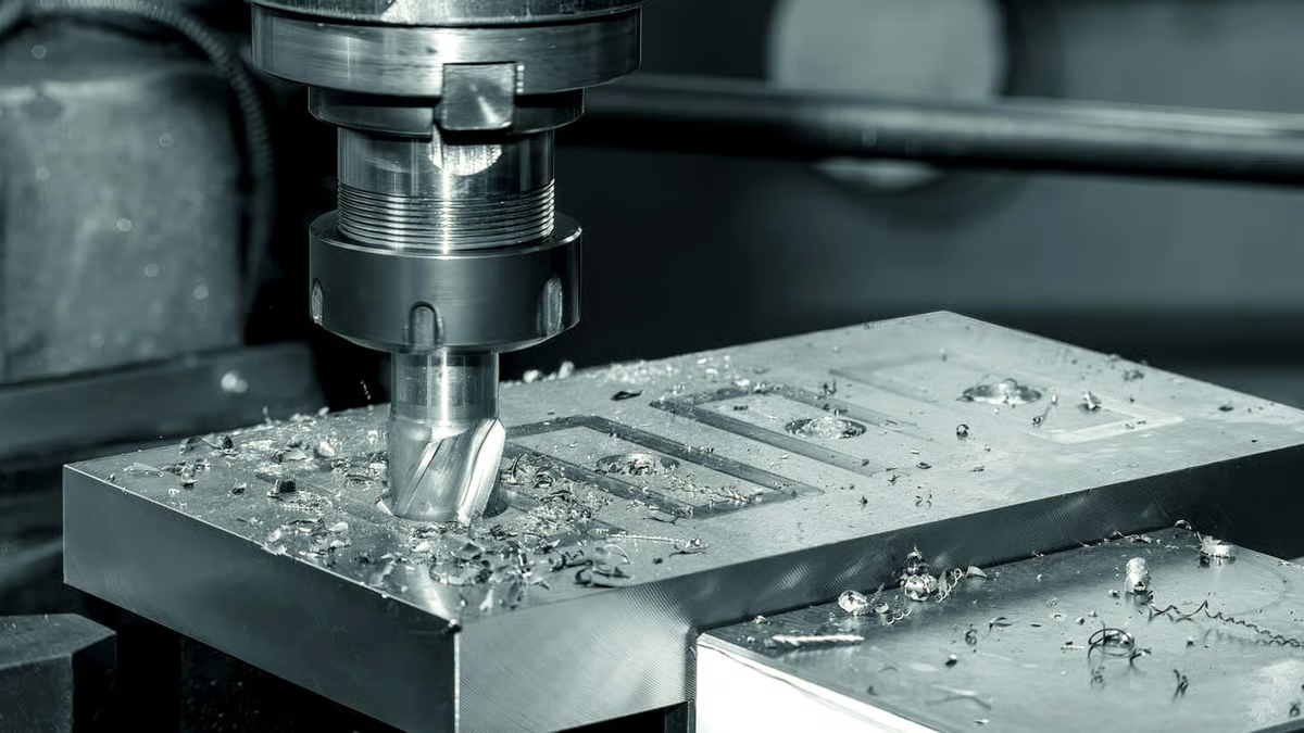
Start with the teeth. A 13-tooth pinion driving a 21-tooth gear gives a ratio of 21/13, or 1.615:1. That is overdrive: output speed rises, output torque falls by the same factor. Swap the driver and driven gears and you get 0.619:1, a reduction that multiplies torque by 1.615.
The theoretical number is only the first line. Real output torque equals input torque times the ratio times mesh efficiency. A single spur mesh runs about 0.98. A worm drive can sit near 0.5 at low ratios. Multiply through before you size the motor, or the extra margin comes out of the housing wall thickness.

A gear pair only behaves the way the drawing says if the shaft centers stay where they were designed. On a two-stage reducer we hold bearing bore position to ±0.005 mm and the bore-to-bore center distance to the same band. That keeps contact near the pitch line instead of the tooth tip.
Bores are cut in one setup on a mill-turn center or a 5-axis machine, so the front face and the back face share a datum. Flip a part between two fixtures and the stack-up alone can eat 0.02 mm. We would rather cut it once and measure it once.
Surface finish matters too. A bore at Ra 1.6–3.2 μm holds a press-fit bearing fine. For a shaft running directly in the housing, we go to Ra 0.8–1.6 μm or finer depending on the fit and the load.

Gear blanks and housings carry different loads, so they get different materials. Housings in 6061-T6 or 6082 keep weight down and machine cleanly. Shafts in 4140 or 4340 take the bending without yielding. Stainless 17-4PH (SUS630) shows up when corrosion and strength both matter.
Heat treat and finish come after the geometry is set. Hardcoat anodizing on a housing adds wear resistance but changes the bore by a few micrometers, so we mask bearing seats. Electroless nickel holds tight tolerances better on a shaft journal.
What each arrangement does to speed and torque.
| Arrangement | Speed | Torque | Typical use |
|---|---|---|---|
| Reduction (i > 1) | Falls by the ratio | Rises by the ratio × efficiency | Robot joints, winches, conveyors |
| Overdrive (i < 1) | Rises by the ratio | Falls by the ratio × efficiency | Spindle drives, pump inputs |
| Direct (i = 1) | Unchanged | Unchanged minus bearing drag | Coupling two shafts in line |
| Compound train | Product of all stages | Product of all stage ratios | High reduction in a short housing |
One shop for the housing, the shafts, and the small hardware around them.
Bearing bores, seal grooves and mounting faces cut in one setup to keep center distance on the drawing.
Turned and ground journals, keyways, splines and shoulders held to ±0.005 mm where the bearing sits.
Blanks and finished bore-and-face features. We machine the body; hobbing and grinding are quoted with the same lot.
Bolt patterns, pilot diameters and register fits for motor and reducer interfaces.
5-axis cuts on thin ribs and angled pads without a second fixture or a weld.
One unit or 10,000. The same drawing, the same inspection sheet, the same datum.
Numbers you can design against.
| Item | Range | Notes |
|---|---|---|
| Tolerance | ±0.005 mm (±0.0002 in) | On critical bores and journals |
| Surface finish | Ra 0.2–0.8 μm fine | Ra 0.8–1.6 μm on bearing fits |
| Max part size | 4,000 mm | Larger travel: 4,000 × 400 × 150 mm |
| Rotary work | Ø400 mm table | 4-axis indexing for bolt circles |
| Materials | Al, SS, steel, Cu, Ti | 6061, 4140, 17-4PH, Ti-6Al-4V |
| Inspection | 100% before shipment | Reports on request |
Six reasons engineers send us the parts that set backlash.
Fifteen years of turning and milling parts that have to fit on the first assembly.
The same band we hold on bearing bores applies to shaft journals and register fits.
Mills, lathes and mill-turn centers across three plants. No single machine becomes the bottleneck.
Send a model in the morning and get a quote with DFM notes the same day.
Raw material check, in-process monitoring and final inspection on every lot.
One prototype gearbox or a 10,000-part run. No setup fee gating a first article.

Joint housings and harmonic drive adapters where backlash shows up as position error.

Reducer covers, motor mounts and sensor brackets that bolt to a fixed interface.
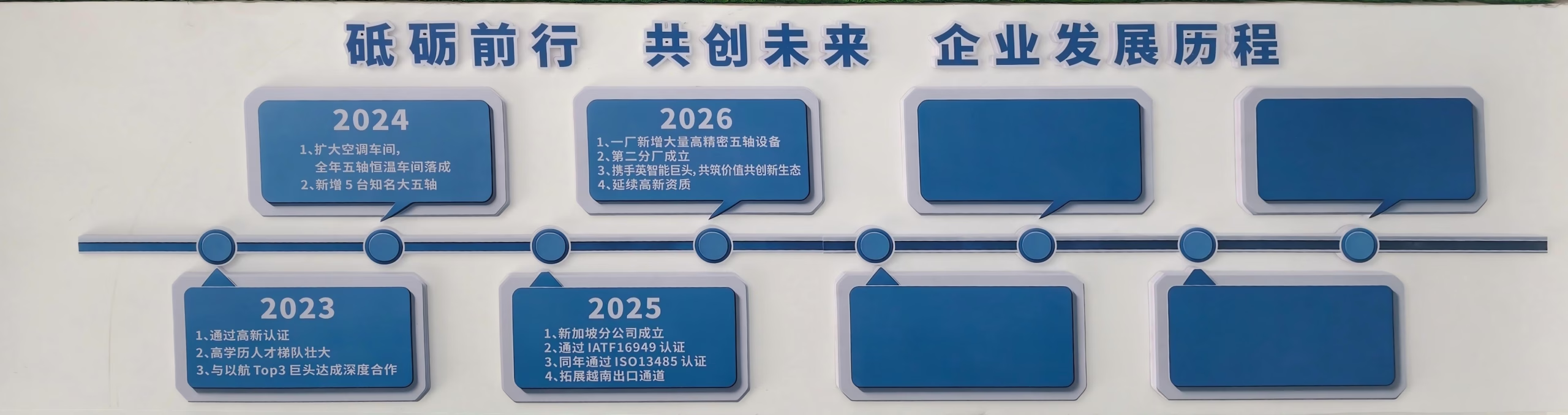
Gearbox housings and shafts that run for years, so bore alignment decides service life.
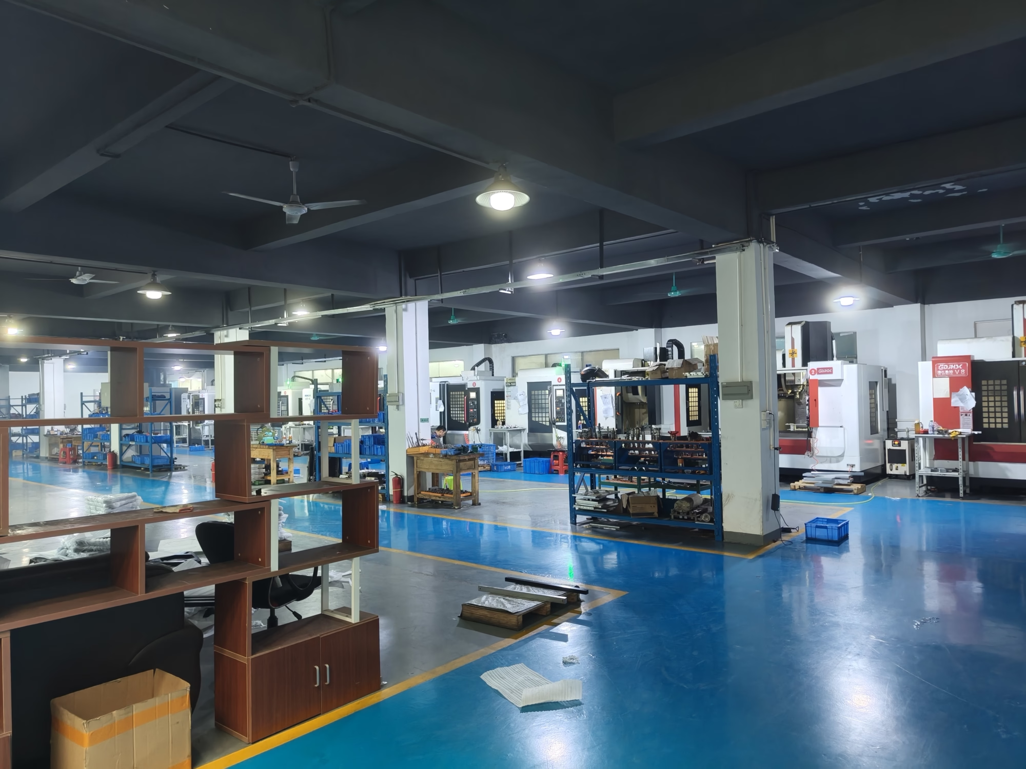
Actuator housings and gear blanks where weight and stiffness are both constrained.
Only if the ratio number is greater than one and you mean a reduction. A 1.615:1 reduction takes input torque and multiplies it by 1.615, minus mesh losses. An overdrive with the same number does the opposite and cuts output torque.
Past a point, more reduction stops being free. Multi-stage trains add mesh losses, and a very high single-stage ratio on a worm drive can drop efficiency near 0.5. The torque budget, not the ratio, decides the limit.
Take input torque, multiply by the ratio, then multiply by the mesh efficiency. For a 2 N·m input, a 4:1 reduction and a 0.97 spur mesh, output is about 7.76 N·m at the shaft.
That figure is static. Under acceleration, add the inertia of the driven parts reflected back through the ratio squared. For reversing axes, check backlash separately because it changes the position, not the torque.
A well-lubricated spur or helical mesh runs about 0.97 to 0.99 per stage. Use 0.97 for sizing and you leave yourself a little margin.
Bevel and worm drives are different. Worm efficiency depends on the lead angle and drops quickly at low ratios. Below about 10:1, plan for 0.5 to 0.7 and check the heat the losses put into the oil.
Backlash is the gap between non-working flanks. Under one direction of torque, the driving flanks stay in contact and the gap sits on the other side. Reverse the load and the teeth cross that gap before they carry torque.
The measured number also grows with wear and with housing deflection. If the axis needs tight bidirectional position, preload or a split gear is usually the answer, not a smaller nominal backlash.
Tighter than most people expect. Center distance error moves the contact point along the tooth profile, and the teeth stop meeting near the pitch line. A few hundredths of a millimeter is enough to raise noise and load the tips.
We hold bearing bore position and center distance to ±0.005 mm on critical housings and cut both bores from one datum so the number survives assembly. If the design allows a floating idler or an adjustable mount, you can relax that band.
Yes. Housings, covers, shafts, gear blanks, flanges and brackets all run through the same shop. That means one drawing set, one inspection sheet and one shipment instead of three vendors arguing about which part caused the interference.
We hold ISO 9001:2015, IATF 16949:2016, ISO 13485:2016 and ISO 27001:2022. Uploads stay confidential and we sign an NDA on request.
A 3D model or a 2D drawing with the critical dimensions marked. Tell us the fit class on bearing bores, the material, the finish and whether the part sees reversing load.
A STEP file and a note on the function is usually enough. We return a quote with DFM notes within 12 hours, and production can start within 24 hours of a released drawing.
No. We run from one prototype to 10,000+ part runs. A single housing for a test rig goes through the same inspection as a production lot.
Prototype parts typically ship in 3–5 days. Larger runs get a schedule with the quote so you can plan the assembly line around it.
Upload a STEP file and get a quote with DFM notes within 12 hours. No minimum order quantity, 100% inspection before shipment.
12-hour quote100% inspectionNo MOQNDA on request
Trusted by engineers and manufacturers worldwide










Upload your 3D model or 2D drawing and get a quotation with a free DFM analysis. Maximum processing size 4,000 mm.
CNC Metals 13 grades
CNC Plastics 10 grades
Machines & processes 12 options
Surface & post-processing 10 options
Material: not selected Machine: not selected Post-process: not selected
Fill in this short form and we'll open WhatsApp with your message ready to send. We only use these details to reply to you.
Nothing is sent until you press send inside WhatsApp.