
What Is the Litz Vertical 5 Axis CNC Machining Center?
A vertical 5 axis cnc machining center holds the part in one setup while the spindle and table tilt, so five faces can be cut without re-clamping. This page explains how that mechanism works, which geometry it suits, and where it stops paying off. Written for engineers and buyers who need to judge a part before sending it out.
In this article
- 1
- 2
- 3
- 4
- 5
- 6
- 7
- 8
Key takeaways
What the machine actually is
A vertical 5 axis cnc machining center is a milling machine with a spindle that points down and three linear axes for the tool, plus two rotary axes. The linear axes move the tool in X, Y and Z. The rotary axes tilt either the spindle head or the work table, depending on the machine layout. Litz builds this configuration for shops that cut complex parts from solid stock.
The vertical layout matters. The part sits on a table you can see and reach, chips fall away from the cut, and the operator can check a feature without pulling the part out. That is why vertical machines dominate job shops. A horizontal machine clears chips better on boxy parts, but the vertical format is easier to fixture for the mixed work that reaches a contract shop.
The two rotary axes are usually named A and B, or A and C. A tilts around the X axis. B or C rotates around the vertical axis. On a trunnion machine, the table tilts and rotates the part under a fixed spindle. On a swivel-head machine, the spindle tilts and the table rotates. The cutting result is similar. The difference shows up in how much weight the table can carry and how far the tool has to reach.
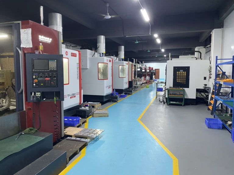
GreatLight runs 16 simultaneous 5-axis machining centers among 127 high-precision CNC machines. The largest travel is 4,000 × 400 × 150 mm, and one machine carries a Ø400 mm rotary table. Those numbers decide what fits, not what is possible.
How five axes cut a part in one setup
On a 3-axis machine, the tool always approaches from the same direction. If a hole sits on a 30° face, you either tilt the part on an angle plate, cut it in a second setup, or leave it for a 5-axis machine. Each re-clamp adds a datum shift. Stack three of them and the tolerance budget is gone before the first chip.
A 5-axis machine keeps the part clamped and moves the tool normal to each face. The tool axis stays perpendicular to the surface, so a face mill or drill enters straight instead of at an angle. Straight entry means even chip load, predictable tool life, and a surface that matches the CAD model.
The rotary axes also let a short, stiff tool reach deep features. A long tool deflects under load and leaves chatter. By tilting the part, you bring the feature closer to the spindle nose and cut with a tool that is three times shorter. That single change often fixes a finish problem that no feed or speed adjustment could solve.
This is the core of the litz vertical 5 axis cnc machining center concept: the part stays still, the geometry moves around it.
- 1Fewer setupsOne clamp instead of three or four, so datums stay stacked in a single coordinate frame.
- 2Normal approachThe tool meets each face at 90°, which keeps chip load even and tool life predictable.
- 3Shorter toolsTilting the work brings deep features within reach of a stiff, short cutter.
- 4Better accessUndercuts and side ports can be reached without a special angled fixture.
Where ±0.005 mm comes from and when it holds
The published tolerance for our 5-axis work is ±0.005 mm, or ±0.0002 in. That is a real number on a real part, but it is a system result, not a machine spec. The machine contributes its own geometric error. The fixture contributes location error. The tool wears. The material moves as it is cut. All four add up, and the total is what the inspector measures.
Thermal drift is the quiet one. A spindle running for two hours grows a few micrometres. On a 20 mm bore, that is nothing. On a 200 mm bore with a tight true position callout, it matters. Shops that hold tight tolerances all day control the room temperature and let the machine warm up before the first cut.
Surface finish follows the same logic. As-machined finish sits around Ra 1.6–3.2 μm. A careful pass on a stable setup reaches Ra 0.8–1.6 μm. Fine finishing with a small stepover and a balanced tool can reach Ra 0.2–0.8 μm, but that is a deliberate operation with its own cycle time, not a default.
The practical rule: check the tolerance against the feature, not the part. A ±0.005 mm bore is routine. A ±0.005 mm true position across a 500 mm casting is a different job, and it needs a conversation before the quote, not after.
Materials that suit this configuration
Five-axis cutting works on any machinable metal, but the payoff changes with the material. Aluminium grades such as 6061, 7075 and 2024 cut fast and let the machine show its speed. Titanium TC4 (Ti-6Al-4V) and Inconel cut slow and hot, so the value comes from fewer setups rather than from cycle time. Stainless 316L and 17-4PH sit in the middle.
Harder materials punish long tools and light setups. That is exactly where the tilt pays off. A 5-axis machine can present a blade root or a thin rib to a short cutter and take a full depth pass, instead of nibbling with a long end mill that sings. The same logic applies to hardened tool steel and to beryllium copper.
Plastics behave differently again. POM, PEEK and carbon fibre composites cut easily but move after the cut. On a 5-axis machine you can machine both sides in one clamp, which removes the flip and keeps the two faces aligned. That matters on a long thin composite bracket where a second setup would shift the hole pattern.
We machine aluminium, stainless, steel, copper and brass, titanium and special alloys, plus engineering plastics. The material list is not a claim about difficulty. It is a list of what has run through the shop.
When a 5-axis center is the wrong choice
A 5-axis machine costs more per hour than a 3-axis machine. If the part is a flat plate with holes drilled from one side, the extra axes sit idle while the meter runs. A 3-axis mill with a good fixture will hit the same tolerance, ship sooner and cost less. Sending that part to a 5-axis cell is a waste of capacity on both sides.
Rotary axes also add limits. A trunnion table has a swing diameter. A part that is long and tall may hit the table or the enclosure wall when it tilts. Reach matters too: a deep pocket far from the rotary centre may need a tool extension that cancels the stiffness gain you came for. The machine travel numbers tell you what fits.
Programming and setup time are real costs. A 5-axis toolpath needs collision checking, and the post-processor must match the machine kinematics. First-article inspection takes longer because there are more faces to check. On a one-off part, that overhead can exceed the machining time.
The honest test is simple. Count the setups on a 3-axis machine. If the answer is one, and no feature needs an angled approach, use the 3-axis machine. If the answer is three or more, or the part has curved faces, angled ports or undercuts, the 5-axis route usually wins on total cost, not just on quality.
How we set up and inspect the work
Every job starts with a DFM review, and we return a quotation with that analysis within 12 hours. The review checks wall thickness, tool reach, corner radii and datum strategy before anything is cut. Finding a problem at that stage costs nothing. Finding it after the first article costs a week.
Production can start within 24 hours of approval, and parts usually ship in 3–5 days. That schedule depends on material stock and on how many operations the part needs. We do not quote a date we cannot hold, and our historical late-delivery probability is below 2%.
Inspection is 100% before shipment. Raw material is checked on arrival, the process is monitored while the part is cut, and the finished part gets a final check. Reports are available on request. We hold ISO 9001:2015, IATF 16949:2016, ISO 13485:2016 and ISO 27001:2022, which map to the general, automotive, medical and information-security requirements our customers audit against.
Files stay confidential. Uploads are handled under our security controls, and an NDA is available on request. There is no minimum order quantity, so a single prototype and a 10,000-part run go through the same process.
3-axis, 4-axis or 5-axis: picking the right machine
Compare by part geometry, not by machine prestige
| Part feature | 3-axis | 4-axis | 5-axis |
|---|---|---|---|
| Flat plate, holes on one face | Best fit | Overkill | Wasteful |
| Holes on four side faces | Two or more setups | Good fit | Works, costs more |
| Angled port or boss | Needs angled fixture | Sometimes | Best fit |
| Curved blade or impeller | Not practical | Rarely | Best fit |
| Deep pocket, long tool | Chatter risk | Same risk | Tilt shortens the tool |
| Undercut, no special fixture | Not reachable | Limited | Best fit |
| One-off simple bracket | Best fit | Overkill | Overkill |
| Tight true position, 5 faces | Datum stack grows | Two setups | Best fit |
The verdict
If the part needs three or more setups on a 3-axis mill, or has curved faces, angled ports or undercuts, use the 5-axis route. If it is a flat plate with holes on one side, stay on a 3-axis machine and spend the saving on a better fixture.
Questions engineers ask next
Does a 5-axis machine always hold tighter tolerance than a 3-axis machine?
No. The machine's own accuracy is only one input. A 3-axis machine with a rigid fixture and one clean datum can beat a 5-axis machine that is chasing a loose setup.
The 5-axis advantage is geometric. It removes setups, so it removes the datum shifts that come with them. On a part with five machined faces, that is where the accuracy gain comes from.
How large a part can you machine?
Our largest travel is 4,000 × 400 × 150 mm. Other machines cover 750 × 1,150 × 550 mm, 600 × 600 × 600 mm, 500 × 500 × 450 mm and 500 × 310 × 200 mm.
Fit is not only about travel. A part that tilts on a trunnion must clear the table and the enclosure through the whole rotary range. Send the model and we will confirm the setup.
What surface finish can I specify?
As-machined is typically Ra 1.6–3.2 μm. A controlled finishing pass reaches Ra 0.8–1.6 μm. Fine finishing can reach Ra 0.2–0.8 μm when the geometry allows it.
Specify finish per face, not for the whole part. Polishing a face that bolts to a frame adds cost with no function.
How do you handle first-article inspection on a complex part?
We inspect 100% of parts before shipment, with raw material checks, in-process monitoring and a final inspection. Dimensional reports are available on request.
For a first article, agree the critical features and the datum scheme before cutting. That list drives the inspection plan and avoids arguments about which dimensions matter.
Can you machine a single prototype?
Yes. There is no minimum order quantity. One prototype and a 10,000-part run go through the same quotation and inspection process.
Quotation and DFM analysis come back within 12 hours, and production can start within 24 hours of approval.
What do you need to quote a 5-axis part?
A STEP or native CAD file, the material, the critical tolerances, the surface finish per face, and the quantity. Callouts on the drawing override general notes.
If the part has an angled feature, mark which datum it is measured from. That single note prevents most of the back-and-forth on a first order.
Send a part and get a real answer
Upload your model and we will return a quotation with a free DFM analysis within 12 hours, plus a straight answer on whether the part belongs on a 5-axis machine.
12-hour quote100% inspectionNo minimum orderNDA on request
More machining notes
We publish setup notes, tooling trials and inspection data from the factory floor.











