
What Makes the 3 Axis CNC Surface Grinding Machine Unique
A 3 axis CNC surface grinding machine removes material with an abrasive wheel, not a cutting tool. That single difference sets the flatness, parallelism and surface finish it can hold. This page explains how the three axes move, what the process can and cannot do, and how to tell whether a part belongs on a grinder or a mill.
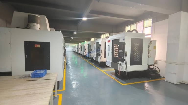
How a 3 axis CNC surface grinding machine actually cuts
Grinding is a chip-removal process, but the chip is tiny. A vitrified or resin-bonded wheel spins at 20–35 m/s, and each abrasive grain takes a sliver of material measured in micrometers. The result is a scratch pattern far finer than any end mill can leave. On a 3 axis CNC surface grinding machine, that wheel travels in three linear directions: X for table stroke, Y for cross-feed, Z for down-feed into the work.
Milling and grinding differ in more than grit size. A milling cutter has a fixed number of edges, so its feed rate is set by tooth count and spindle speed. A grinding wheel has thousands of cutting points that renew themselves as the bond wears. Feed is programmed as table speed, cross-feed stepover and down-feed per pass, usually 0.005–0.02 mm for a finishing pass.
Heat is the main risk. Nearly all the energy of a grinding pass turns into heat at the contact zone. Coolant floods that zone, and a soft wheel grade keeps the abrasive sharp instead of glazed. If the wheel loads up, the part burns and the surface hardens in patches. A burn mark can pass a visual check and still fail a hardness or fatigue test later.
Rigidity decides the achievable flatness. The wheel spindle, the table ways and the column all deflect a little under load. A 3 axis grinder is built with short, stiff load paths so that deflection stays inside a few micrometers. That is why grinding can hold ±0.005 mm on a flat face where milling would need a secondary operation.
What each of the three axes controls
The X axis drives the table left and right under the wheel. Stroke length is set slightly beyond the part so the wheel clears both edges on every pass. Table speed on a typical surface grinder runs 5–25 m/min depending on wheel grade and material. Too fast and the wheel cannot finish the cut; too slow and the part burns.
The Y axis moves the wheel or table across the part width. Stepover is usually 50–80% of the wheel width. A wider stepover saves time but leaves a faint witness line where the wheel edge meets the previous pass. A narrower stepover blends those lines out at the cost of cycle time. This is a trade the operator makes per part, not a fixed rule.
The Z axis sets depth of cut. In a manual machine the operator turns a handwheel; in a CNC grinder the controller moves Z in programmed increments and can compensate for wheel wear. Dressing the wheel removes a few hundredths of a millimeter, so the controller offsets Z after each dress. Without that offset, part size drifts upward over a run.
Note what is missing. There is no rotary A or B axis and no second rotary C axis. The wheel stays perpendicular to the table, so the machine grinds flat faces, shoulders, steps and parallel surfaces. It does not grind a compound angle or a contoured flank in one setup. For those, the part is indexed on an angle fixture or moved to a different machine.
When 3 axis CNC surface grinding is the wrong choice
Grinding is slow per unit of material removed. Stock removal rates are a fraction of milling, so nobody grinds a block down from solid. The normal flow is mill close to size, leave 0.1–0.3 mm of stock, then grind to final dimension. If a drawing calls for a flat face on a part with no tight tolerance, milling or face turning is cheaper and faster.
Geometry matters too. A 3 axis surface grinder works best on prismatic parts with accessible flat faces. Deep pockets, internal bores, undercuts and curved surfaces do not fit the process. Internal grinding needs a different spindle; cylindrical grinding needs a workhead. Sending that work to a surface grinder wastes setup time.
Part size has a ceiling. A long bed machine can take a 4,000 mm part, but a small machine with a 500 mm stroke cannot. Weight matters as well, since the table has to accelerate the part on every stroke. Heavy parts slow the table, and slow tables change the grinding behavior. Check the machine envelope before quoting a large plate.
Material choice sets the wheel. Hardened tool steel, stainless and titanium grind well with the right abrasive. Soft aluminium clogs a standard wheel, so it needs a coarse, open-grade wheel and more coolant. Plastics and composites are usually better milled or routed. Grinding them tends to smear rather than cut.
What the process holds, and what changes it
Flatness and parallelism are the two numbers buyers care about most. A well-set 3 axis CNC surface grinding machine holds ±0.005 mm on thickness and keeps two faces parallel within the same band. That matters on seal faces, valve plates, gauge blocks and machine slides, where a few micrometers of taper changes how the part seats.
Surface finish moves with wheel specification. A fine-grit wheel with a light finishing pass reaches Ra 0.2–0.8 μm. A coarser wheel and a heavier pass land around Ra 0.8–1.6 μm. Neither is better in the abstract; the drawing decides. A bearing seat wants the finer finish, a clamping face usually does not.
Thermal drift is the quiet enemy. The wheel, the coolant and the part all warm up during a run. If the machine grinds a batch from a cold start, the first parts can sit a few micrometers off the last ones. Shops that hold tight bands let the machine idle to temperature first, and check the first part before running the rest.
Wheel wear is the second drift source. As the wheel dulls, it pushes instead of cutting, and part size creeps. Dressing restores the edge but changes wheel diameter, so the control has to re-zero. A shop that tracks dress count and size trend will catch drift early. One that checks only the last part will not.
How a grinding job is set up
- 1Inspect the pre-ground partCheck incoming stock and flatness. Leave 0.1–0.3 mm of stock on the face to be ground. Remove burrs first so the part sits flat on the chuck.
- 2Mount and indicateClamp on a magnetic chuck or fixture, then indicate the top face. Aim for under 0.01 mm runout before the first pass. Re-tap the part if it rocks.
- 3Dress the wheelDress with a single-point diamond at 0.01–0.02 mm per pass. A freshly dressed wheel cuts cool and holds size. Dressing also sets the effective wheel width for stepover.
- 4Rough grindTake 0.02–0.05 mm per pass with full coolant. Keep the table moving so the wheel does not dwell and burn one spot.
- 5Finish grindDrop to 0.005–0.01 mm per pass and slow the cross-feed. Spark-out passes at zero down-feed clear the last spring in the system.
- 6Measure and adjustCheck thickness and flatness, then offset Z for wear. Record the size so the next part in the batch starts from a known number.
Grinding versus milling for flat faces
Use this to pick a process before you send an RFQ.
| Factor | 3 axis CNC surface grinding | 3 axis CNC milling |
|---|---|---|
| Typical flatness | ±0.005 mm on a prepared face | 0.02–0.05 mm without a finish pass |
| Surface finish | Ra 0.2–0.8 μm | Ra 1.6–3.2 μm as machined |
| Hardened steel above 45 HRC | Cuts it directly | Needs carbide or a post-hardening grind |
| Stock removal rate | Low; 0.1–0.3 mm of stock | High; removes most of the stock |
| Setup and cycle time | Longer per part, tight size control | Shorter, easy to reprogram |
| Best part shape | Flat faces, steps, parallel surfaces | Pockets, contours, complex 3D geometry |
| Distortion risk | Low heat input, needs coolant control | Cutting forces can spring thin walls |
| Cost driver | Wheel wear and dressing time | Machine time and tool wear |
The trade in one line
If the part needs a flat face inside ±0.005 mm, a hard surface, or a finish below Ra 0.8 μm, grind it after milling. If it just needs to be flat and the tolerance is loose, mill it and skip the second operation.
Common questions
How is 3 axis grinding different from 5 axis grinding?
A 3 axis grinder moves the wheel in X, Y and Z only, so the wheel stays square to the table. It grinds flat faces, steps and parallel surfaces.
A 5 axis grinder adds two rotary axes, so the wheel can tilt and the part can rotate. That lets it grind angles, tapers and contoured forms in one setup. The trade is cost, programming time and a longer setup.
Which materials can be ground on a surface grinder?
Hardened tool steel, stainless steel, titanium and cast iron all grind well with the right abrasive and coolant. Materials above 45 HRC are often ground because milling them is slow and wears tools fast.
Soft aluminium, copper and plastics need a coarse, open-grade wheel and heavy coolant, or they clog the wheel and smear. In many cases they are better milled instead.
Why does surface finish matter on a functional part?
Finish controls how a surface behaves, not just how it looks. A finer finish reduces friction and wear on sliding faces, improves seal contact, and removes the micro-notches where fatigue cracks start.
On a sealing or bearing surface, going from Ra 1.6 μm to Ra 0.4 μm can change leakage and service life. That is why the drawing usually specifies a number rather than a visual standard.
Can 3 axis surface grinding run in production quantities?
Yes. Once the wheel, feeds and dress interval are fixed, the process repeats within a few micrometers part to part. The limit is cycle time, not repeatability.
For a run of thousands, the shop usually fixtures several parts at once, grinds them in one pass and checks a sample against the size trend. Wheel wear is tracked so a mid-run dress does not shift the batch.
What causes a burned or checked surface during grinding?
Burns come from heat. A glazed or loaded wheel, too deep a pass, or too little coolant all push temperature up at the contact zone. The surface discolors, and the layer under it can harden and crack.
The fix is mechanical, not cosmetic. Re-dress the wheel, lower the down-feed to 0.005–0.01 mm, and increase coolant flow. Re-grinding the surface removes the damaged layer, but only if enough stock remains.
Send a flat part and get a real answer
We grind flat faces to ±0.005 mm and Ra 0.2–0.8 μm on parts from one piece to 10,000+. Upload a drawing and we will confirm whether grinding is the right step or a waste of your budget.
12-hour quoteFree DFM analysis100% inspection
More from the shop floor
We publish setup notes, tooling trials and inspection data from the factory floor.











