
10W Laser CNC: 5 Essential Tips to Maximize Precision and Slash Production Costs
A 10W laser is a finishing tool, not a cutting torch. This page walks through the five variables that decide whether your parts hold tolerance or drift: focus, process window, thermal control, nesting, and feedback. Written for engineers and production managers who already run a laser module on a CNC frame and want fewer scrap cycles.
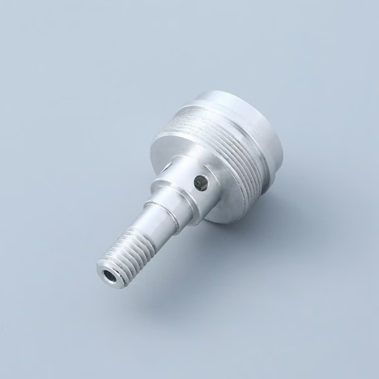
What a 10W laser module can and cannot do
Five tips, in the order they affect your scrap rate.
Focus calibration and beam delivery decide everything downstream
Spot size sets power density, and power density sets kerf width. Move the lens 1 mm off the focal plane on a 10W diode module and the spot can grow from roughly 0.1 mm to 0.3 mm. Energy density drops by about an order of magnitude. The cut gets wider, the edges char, and a part you designed at ±0.05 mm comes out at ±0.15 mm. No parameter table fixes that.
Set focus with a gauge, not by eye. Run a ramp test on scrap of the same alloy and thickness: tilt a plate a few degrees under the head, fire a single line, then measure the narrowest point under a tool microscope. That point is your true focal offset, and it changes when you swap lenses or change nozzle standoff. Record it per lens and per material.
Beam delivery matters as much as focus. A dirty window, a chipped lens, or a loose mirror mount scatters light before it reaches the work. Check optics at the start of every shift with a lint-free swab and isopropyl alcohol. Air assist should be clean, dry, and aimed coaxially; oil or moisture in the line shows up as spatter on the lens within hours.
- 1Measure, do not guessRamp test on scrap gives the real focal offset for each lens and material.
- 2Keep a focus logNozzle standoff, lens part number, and measured offset per job.
- 3Inspect optics dailyA 5-minute swab beats a ruined lens and a week of bad parts.
Build a process window per material instead of tuning per part
Operators who tune settings for every new job never escape trial and error. The fix is to define a window: a range of power, feed, and pass count that produces an acceptable result on a given material and thickness. Once the window exists, new geometries inherit it and you only adjust for edge cases.
Start with a matrix. For each material and thickness, run a grid of feed rates at fixed power, then repeat at a second power level. Mark each cell pass or fail against three criteria: kerf width, edge quality, and depth consistency across the part. The pass cells form your window. For thin stainless and aluminium sheet, three to five passes at moderate feed usually beats one slow pass, because the material clears before heat builds.
The table below is the kind of record we keep for our own laser work. Treat the numbers as starting points, not gospel. A 10W diode module from one supplier behaves differently from a DPSS unit at the same nominal power, and coating thickness changes absorption on anodized aluminium.
When a window does not exist, that is a signal. If every combination produces charring or incomplete depth, the geometry is wrong for a 10W source. A 0.8 mm deep slot in 3 mm steel is a milling job, not a laser job.
Reference process windows for a 10W laser module
Verify on scrap of the exact alloy and thickness before running production.
| Material and thickness | Passes | Focus set | Watch for |
|---|---|---|---|
| Anodized aluminium, 1 mm | 2–3 | Surface focus | Coating flaking at edges |
| Stainless 304, 0.5 mm | 3–4 | Slight defocus | Dross on the underside |
| PMMA, 2 mm | 2 | Surface focus | Hazing and micro-cracks |
| ABS, 1.5 mm | 2–3 | Surface focus | Melt lip and stringing |
| HDPE, 2 mm | 3 | Slight defocus | Fume deposits on lens |
Thermal control: the heat you cannot see is the tolerance you lose
A 10W beam does not cut by brute force. It works by concentrating energy, and whatever is not carried away in the kerf stays in the part as heat. Thin sheet warps. Plastics soften and re-solidify with a raised lip. Acrylic develops micro-cracks that show up two days later in a drop test.
Three controls do most of the work. First, air assist: clean, dry, regulated at a steady pressure, aimed to blow ejecta back and away from the lens. Second, dwell management: add small delays between passes so the kerf can cool. A 0.2 s delay per pass costs little cycle time and prevents cumulative heat. Third, fixturing: a vacuum table or a pin fixture pulls heat out and stops thin parts from lifting into the beam.
Ambient conditions matter more than most shops admit. A laser head that was aligned at 20 °C drifts when the bay reaches 32 °C in summer, because the lens tube and the machine frame expand at different rates. Keep laser bays within a controlled band and re-check focus after any long machine stop or after moving the head. Log the ambient temperature with each process window so the record stays usable across seasons.
On materials that are thermally sensitive, consider running the laser as a secondary operation after CNC machining rather than before. Engraving a finished, stress-relieved aluminium face yields a cleaner result than engraving a rough blank that will move during the next milling pass.
- 1Inter-pass delay0.2 s per pass reduces heat buildup on thin stock.
- 2Vacuum fixturingPulls heat down and stops thin parts lifting into the beam.
- 3Temperature loggingRecord ambient temperature with each saved window.
Nesting and toolpath strategy cut cost more than power settings
Most of the cost in a laser job sits in setup, handling, and scrap, not in the beam. Nesting attacks all three. A tighter nest uses less stock, which matters directly when you are running 316 stainless or titanium. It also shortens total travel, which reduces cycle time and lets the head dwell less between features.
Sequence the cuts so that internal features go first and the outer contour goes last. If you cut the perimeter first, the part can shift or drop, and the remaining internal cuts land off-centre. For parts held on a vacuum table, leave small tabs and cut them in a second pass so the part stays anchored through the engraving step.
Group jobs by material and thickness rather than by customer. Two different parts in the same 1 mm anodized aluminium can share one setup, one focus check, and one air-assist setting. This is where a process window pays for itself twice: it lets you combine jobs that a per-part tuning habit would keep separate.
For production volumes, consider whether the laser should run at all. Laser marking and engraving on a milled part is often the right call for serial numbers, logos, or datum labels, with a minimum character height of 1.5 mm. But if the feature has depth in metal, milling will hold tolerance better and produce no heat-affected zone. We run both in the same shop, and the split is usually obvious once you compare feature depth to beam capability.
In-process inspection and closed-loop feedback close the gap
A laser process drifts. Lens contamination builds, the focal offset moves, ambient temperature shifts, and a window that passed on Monday starts producing 0.12 mm kerfs on Friday. Sampling at the end of a run only tells you how many parts you have to scrap.
Measure earlier. On a CNC frame, you already have the motion system and often a probe or vision camera. Check the first part of every run against kerf width and a critical feature. If the shop has a vision system on the spindle, measure kerf after the first few passes and adjust feed or pass count before the rest of the nest is cut. Without vision, pull the first part and inspect it on an optical comparator; the 10 minutes cost less than a scrapped sheet.
Keep the feedback loop simple. Record what changed, not just what was measured. A kerf that grew 0.03 mm after a lens change points at focus; the same growth without a lens change points at contamination or thermal drift. That distinction is what makes the next correction fast.
When the laser runs as a step inside a larger CNC workflow, put it under the same quality system as the rest of the process. At GreatLight, machined and laser-marked parts go through raw material check, in-process monitoring, and final inspection, with reports on request. The laser step is not exempt just because it is fast.
- 1First-part checkMeasure kerf and one critical feature before the full nest runs.
- 2Log the changeNote what shifted, not only the measurement itself.
- 3Same quality systemLaser steps get the same inspection discipline as milling.
Common questions on 10W laser CNC work
Can a 10W laser cut metal, or is it only for engraving?
It can cut thin metal, but the practical range is narrow. Stainless and aluminium below about 0.5 mm are workable with multiple passes and clean air assist. Thicker metal needs a fiber or CO₂ source with far more power.
For metal parts with real depth, milling holds tolerance better and leaves no heat-affected zone. We usually recommend the laser for marking, engraving, and light cutouts, and CNC machining for structural features.
How do I know if my part is a good fit for a 10W laser process?
Check three things: material, thickness, and feature depth. Thin sheet in anodized aluminium, stainless 304, ABS, PMMA, or HDPE are good candidates. Engraving and marking on finished parts are almost always suitable.
If the feature needs depth in metal, or the tolerance is tighter than ±0.05 mm, plan on milling. Send the drawing and we will tell you which process fits before you commit to tooling.
What tolerance can I expect from laser engraving on a machined part?
Positional accuracy for engraved text and logos on a CNC frame typically follows the machine, not the laser. The laser adds a small kerf, so plan for a minimum character height of 1.5 mm and keep line weights above the spot size.
Where the part also needs dimensional accuracy, we machine to ±0.005 mm and finish to Ra 0.2–0.8 μm, then apply the laser marking as a secondary operation.
Why does my kerf width change between runs with the same settings?
The usual causes are lens contamination, focal offset drift, and ambient temperature. A dirty window scatters light and widens the effective spot. A head aligned in a cool bay can drift when the shop warms up.
Re-run the ramp test after any lens change or long stop, and log ambient temperature with each saved process window. If the offset moves and the optics are clean, the problem is thermal, not optical.
Does nesting software really reduce cost on a 10W laser?
Yes, but mostly through material yield and handling, not beam time. A tighter nest uses less sheet, and grouping jobs by material and thickness removes repeated setup and focus checks.
Cut internal features before the outer contour, and use tabs on vacuum-held parts so the part stays anchored through engraving. Those two habits prevent rework more often than parameter tuning does.
Can GreatLight run laser marking and CNC machining in one order?
Yes. We machine to ±0.005 mm on 127 high-precision CNC machines, including 16 simultaneous 5-axis centers, then apply laser marking and engraving as a finishing step alongside anodizing, plating, and bead blasting.
Uploads are secure and confidential, an NDA is available on request, and we quote with a free DFM analysis within 12 hours.
Send the drawing, get a process recommendation
Tell us the material, thickness, and where the laser feature sits. We will confirm whether a 10W laser step fits or whether milling is the better route, and return a quote with DFM notes within 12 hours.
12-hour quote±0.005 mm tolerance100% inspectionNDA on request









