
5 Essential CNC Vslot Selection Tips to Maximize Performance and Cut Costs
A V-slot is an alignment feature, a slide track, or a seating face. If the flank angle drifts or the root tears out, the whole assembly suffers. This guide is written for design engineers and buyers who specify V-slots on aluminum, stainless, and titanium parts. After reading it you can judge a quote, a toolpath plan, and an inspection report on your own.
In this article
- 1
- 2
- 3
- 4
- 5
- 6
- 7
- 8
Key takeaways
CNC vslot selection starts with process validation, not a tolerance claim
Every supplier brochure says ±0.005 mm. Very few can hold it across a 300 mm V-slot rail on a warm afternoon. The tolerance you get depends on machine condition, spindle runout, thermal drift, and how often the operator stops to measure. Ask what the shop does between the first article and the last one.
A V-slot is not a simple channel. The two flanks are a matched pair. If the angle opens by 0.1° over the length, a sliding block will rock. If the root shifts 0.05 mm, the block seats at the wrong height. That is why the useful question is not "what tolerance can you hold" but "how do you prove the flank is where I modeled it".
For aluminum 6061 and 7075, a well-maintained three-axis or five-axis machine holds ±0.005 mm on a 200 mm slot without heroics. On 316 stainless or Ti-6Al-4V, the same feature pushes tool wear and heat into the cut. The shop needs a spare tool strategy and a mid-run check. If nobody mentions tool life, the second half of the batch is where the drift appears.
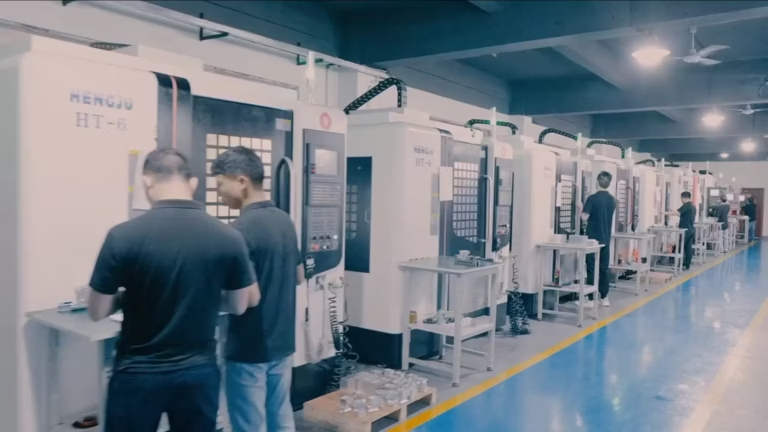
Our own floor runs 127 high-precision CNC machines, including 16 simultaneous 5-axis centers. We verify material and finished parts in-house. That equipment only matters if it is used on your job, so ask which machine will cut the slot and what the last calibration record shows.
- 1Ask for the machine, not the brandA 5-axis center and a worn 3-axis mill do not produce the same V-slot.
- 2Ask when the tool was last changedFlank finish drops fast after 60–70% of tool life on stainless.
- 3Ask for the calibration dateA machine that has not been checked this quarter cannot back a ±0.005 mm claim.
Match the CNC vslot toolpath to the material to avoid chatter
Chatter leaves a rippled pattern on both flanks. It is easy to see and hard to polish out. It comes from a tool that is too long for the depth, a feed that is too high for the flute count, or a setup that lets the part ring. On a deep V-slot, the tool sticks out far and the whole assembly starts to vibrate.
In 6061 aluminum, a two-flute carbide cutter at 8,000–12,000 rpm and 1,500–2,500 mm/min removes material cleanly. In 316 stainless, drop to 1,200–2,000 rpm with a four-flute coated tool and 200–400 mm/min. In Ti-6Al-4V, slower still, plus high-pressure coolant. These are starting ranges, not recipes; the sound and the chip color tell you more than the numbers.
The trap is a single finishing pass with a form tool. It looks efficient. In practice, a form tool cutting both flanks at once loads the spindle in two directions and amplifies any runout. Rough the slot with a smaller end mill, leave 0.2–0.3 mm on each flank, then finish with a sharper tool and a lighter radial step.
If the slot is deeper than 4× the tool diameter, expect to reduce feed by 20–30% and add a mid-cut check. A slot that is 6 mm wide and 30 mm deep is a different job from the same slot at 12 mm deep. The quote should look different too.
- 1Rough then finishLeave 0.2–0.3 mm on each flank for the finishing cutter.
- 2Watch the depth ratioBeyond 4× tool diameter, reduce feed and check the part mid-cut.
- 3Do not force one form toolIt loads both flanks at once and makes runout worse, not better.
Read surface finish as the first signal of CNC vslot quality
Surface finish on a V-slot is not cosmetic. The flanks are sliding or seating surfaces in most fixtures and automation rails. A rough flank wears the mating block and changes the clearance after a few hundred cycles. The finish callout is a functional requirement, so it belongs on the drawing.
As-machined aluminum lands at Ra 1.6–3.2 μm with a normal finishing pass. A good V-slot for a sliding block sits at Ra 0.8–1.6 μm. Hardcoat anodized or polished flanks go finer, Ra 0.2–0.8 μm, but that adds a step and cost. Decide which one the function needs before the quote, not after.
Look at the root as well as the flanks. A sharp root concentrates stress and chips the cutter tip. A root radius of 0.3–0.5 mm costs nothing extra and extends tool life. If your drawing calls for a dead-sharp root, expect either a broken tool or a hand-finishing operation.
When parts arrive, run a fingertip check along the flank and look at the light reflection. A consistent sheen means a consistent toolpath. A banded or blotchy finish means the feed changed mid-cut, and the angle probably changed too.
- 1Functional finishRa 0.8–1.6 μm is the working range for sliding V-slots.
- 2Add a root radius0.3–0.5 mm avoids cutter chipping and stress concentration.
- 3Inspect with lightBanded reflections show a feed change, which usually means angle drift.
Design for manufacturability: keep the V-slot simple to cut
Most expensive V-slots are expensive on the drawing, not on the machine. A 60° included angle with a defined root radius, a depth-to-width ratio under 3, and a clear tool entry from one end is a straightforward job. A 45° slot with a sharp root, a blind end, and a 0.4 mm corner radius is a different story.
Give the cutter room. If the slot runs to a shoulder, the tool needs clearance to exit or the corner will be left as a radius you did not ask for. State the corner condition you can accept. Undercuts and T-slots need a special cutter or an EDM step, and both change the price.
Keep the angle standard where you can. 60° and 90° included angles use common cutters. Odd angles need a custom ground tool, which adds setup cost and lead time even for one part. If the assembly allows 90°, use 90°.
Tolerance placement matters too. A tight tolerance on the flank angle and a loose tolerance on the overall length is normal and cheap. The reverse is a trap: a tight length tolerance on a thin wall will move after machining, and the shop will fight it.
- 1Depth-to-width under 3Deeper slots need reduced feed and more inspection time.
- 2Standard angles60° and 90° use off-the-shelf cutters; odd angles need custom grinding.
- 3Tolerance where it functionsTight on the flank angle, loose on non-critical length.
Close the communication gap before the CNC vslot is cut
The most common failure is not a bad machine. It is a model and a drawing that disagree. The 3D file shows a 60° slot; the 2D drawing calls out a 59° angle from an older revision. The shop cuts one of them and ships. Nobody notices until assembly.
Send one controlled package: the STEP file, a PDF drawing with the critical V-slot dimensions, the material and temper, the finish callout, and the inspection points you care about. Mark the datum. If the datum is the slot root, say so. If it is an outer face, say that instead.
Ask for a DFM review before the quote is final. A shop that flags a deep slot, a sharp root, or a non-standard angle in the first reply is reading the part. A shop that only sends a price is not. Our quotation and DFM analysis come back within 12 hours, and production can start within 24 hours once the package is clear.
On repeat orders, freeze the revision. A slot that moved 0.1 mm between revision C and revision D will produce a scrap batch if the shop is still working from C. The fix is boring: one revision number, one drawing, one confirmation email.
- 1One package, one revisionSTEP plus a dimensioned PDF with the same angle and datum.
- 2Name the datumSlot root or outer face, not both, and not implied.
- 3Request DFM feedbackA useful reply mentions the slot geometry, not just the price.
How to specify and verify a V-slot, step by step
Use this order when you release a new V-slot part or move an existing one to a new shop.
- 11. Define the function firstDecide whether the slot is an alignment feature, a slide track, or a seating face. The function sets the flank angle tolerance, the finish, and the inspection method.
- 22. Set the angle and root radiusUse 60° or 90° included where possible. Add a 0.3–0.5 mm root radius unless the function truly needs a sharp corner.
- 33. Check the depth-to-width ratioKeep it under 3 if you can. Between 3 and 4, expect a feed reduction. Above 4, plan a mid-cut check and a higher price.
- 44. Assign the finish calloutRa 0.8–1.6 μm for sliding flanks, Ra 1.6–3.2 μm for non-contact seating. Put the number on the flank, not on the whole part.
- 55. Pick the datum and inspection pointsName one datum, usually the slot root or a machined outer face. List the flank angle, root position, and width as the checked features.
- 66. Release one controlled packageSTEP file, dimensioned PDF, material and temper, finish, and inspection points. All from the same revision number.
- 77. Ask for DFM feedback with the quoteRead the reply for comments on slot depth, root radius, and angle. Silence on geometry usually means nobody looked.
- 88. Verify the first article before the runMeasure flank angle and root position on the first part. Approve the setup, then let the batch run with in-process checks.
What to specify for common V-slot applications
Match the row to the way the slot is used, then set the drawing callouts.
| Application | Angle and root | Finish target | Inspection focus |
|---|---|---|---|
| Sliding block track | 60° included, 0.3 mm root | Ra 0.8–1.6 μm | Flank angle over full length |
| Static alignment feature | 90° included, 0.5 mm root | Ra 1.6–3.2 μm | Root position and width |
| Seating face for a plate | 60° or 90°, 0.4 mm root | Ra 0.8–1.6 μm | Flank flatness and depth |
| Robotics linear rail | 60° included, 0.3 mm root | Ra 0.2–0.8 μm | Angle, finish, and straightness |
| Thin-wall enclosure slot | 90° included, 0.5 mm root | Ra 1.6–3.2 μm | Wall thickness after cutting |
| Hardcoat anodized slide | 60° included, 0.4 mm root | Ra 0.8–1.6 μm before coating | Pre-coat dimensions and mask |
| Stainless fixture slot | 60° included, 0.3 mm root | Ra 0.8–1.6 μm | Tool wear across the batch |
Pick the shop that reads the slot, not the one that only quotes it
A V-slot lives or dies on process control: toolpath, tool wear, thermal drift, and inspection. Choose a supplier who comments on your slot geometry before cutting metal.
V-slot machining questions engineers ask
What flank angle tolerance is realistic on a 200 mm V-slot?
On aluminum 6061 with a stable setup and a finishing pass, ±0.05° over 200 mm is achievable and is what most sliding applications need. Tighter than that adds inspection time more than it adds function.
On 316 stainless or Ti-6Al-4V, tool wear pushes the angle during the run. Plan a mid-run check and a spare finishing tool if the batch is larger than 20 parts.
Should the V-slot be cut before or after heat treatment or anodizing?
Cut the slot before heat treatment only if the drawing allows for distortion. Most V-slots that must stay within ±0.005 mm are cut after heat treatment, then finished by grinding if needed.
For hardcoat anodizing, cut the slot to the pre-coat dimension and let the coating build. Hardcoat adds roughly 0.02–0.05 mm per surface depending on the spec, and masking the flanks is an option if the fit is tight.
How do I inspect a V-slot without a custom gauge?
A CMM with a small stylus can measure both flanks and derive the included angle and root position. That is the usual route for the first article.
For production, a pair of gauge pins or a ground plug that matches the mating block gives a fast go/no-go check. It will not give you a number, but it catches the failures that matter on the line.
Does a deeper V-slot always cost more?
Usually yes, because the tool has to reach further and the feed drops. A slot at a depth-to-width ratio of 2 is a normal milling job. At a ratio of 5, the shop may need a longer tool, several step-downs, and more inspection time.
If the depth comes from a clearance requirement rather than a functional one, check whether the design can use a shallower slot with an offset instead.
Can a form tool cut the whole V-slot in one pass?
It can, but it is rarely the best choice. A form tool loads both flanks at once, doubles the cutting force, and passes any spindle runout straight into the finish.
Roughing with a smaller end mill and finishing with a dedicated cutter gives a better flank finish and a more stable angle, at the cost of one extra tool change.
What information speeds up a V-slot quote?
Send the STEP file, a dimensioned PDF with the flank angle, root radius, width, depth, material and temper, finish callout, and the quantity. State which dimensions are functional.
A clear package lets the shop return a DFM note with the quote rather than a list of questions. Our quotation and DFM analysis come back within 12 hours.
Send your V-slot part for a DFM check
Upload the STEP file and drawing. We reply with a quotation and a free DFM analysis within 12 hours, and production can start within 24 hours.
12-hour quote and DFM±0.005 mm toleranceNo minimum order quantity100% inspection before shipment
More machining notes from the floor
We publish setup notes, tooling trials and inspection data from the factory floor.











