
7 CNC Precision Milling Tips to Maximize Accuracy and Cut Costs
Accuracy and cost are usually decided long before the spindle starts. This guide is for engineers and buyers who need to hold ±0.005 mm without paying for scrap, extra setups or rework. Read it and you can judge which of the seven levers matter on your part.
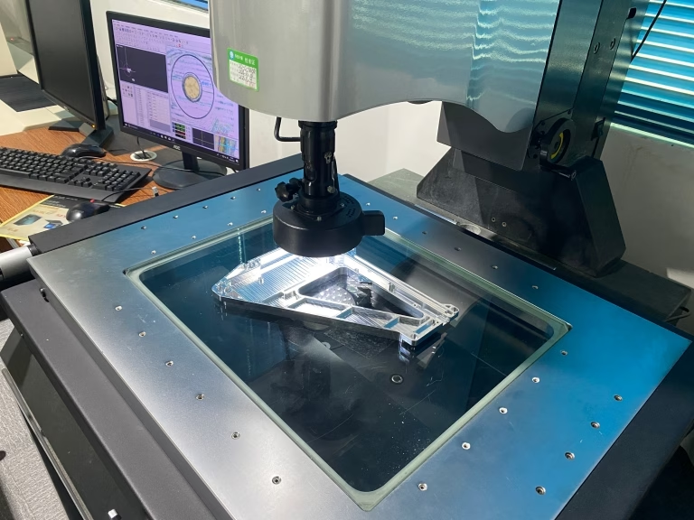
Where accuracy is actually lost
Seven levers, in the order they usually cost you money.
Toolpath strategy decides both cycle time and tolerance
Most tight-tolerance milling problems trace back to the roughing strategy, not the finishing pass. A conventional offset pocket keeps the cutter at full radial engagement, so cutting force rises, the tool deflects, and the wall you machine at 08:00 is not the wall you measure at 16:00. High-efficiency milling changes that. Trochoidal and adaptive paths keep radial engagement low and chip load constant, so the tool bends less and most of the heat leaves with the chip.
Constant chip load also makes the finish predictable. Chatter marks are a dimensional problem as much as a cosmetic one: they show up as taper and as size drift between the first and last part of a run. On aluminium the gain is real. Switching a deep pocket from conventional roughing to adaptive clearing often removes a third of the roughing time and puts less load on a small-diameter cutter.
The catch is CAM time. Adaptive paths need a true stock model, correct holder geometry and a feed rate the machine can actually follow. On a simple open part with one flat face, a plain facing path is faster to program and runs just as well. Use high-efficiency milling where depth of cut is large, tool stick-out is long, or the material is gummy.
Machine rigidity and thermal stability beat raw spindle speed
A 20,000 rpm spindle on a light frame will not hold ±0.005 mm on a 300 mm steel part. Vibration from the structure and the setup goes straight into the surface and into the size. Cast-iron bases, linear guides and a warm-up routine matter more than the rpm number on the spec sheet.
Thermal drift is the quieter problem. A spindle that has run for two hours is not the same machine it was at start-up. On long runs we warm up the spindle, keep the coolant temperature stable and let the shop reach a steady state before the first finish pass. Parts measured straight off a cold machine can be 0.01–0.02 mm off and still pass a spot check.
Rigidity also decides how you can hold the part. Thin-wall aluminium and long shaft features need supports, low cutting force and sometimes a finishing pass with near-zero radial engagement. When a feature is too flexible for any of that, it is a design problem, not a machining problem.
Pick the material grade and temper on purpose
Two parts with the same drawing number and different tempers will not machine the same. 6061-T6 cuts clean and holds a good finish. 7075 machines well and gives higher strength, but it is less forgiving of poor workholding. 304 stainless work-hardens if the feed is too light, which is a common cause of chatter and short tool life.
Condition matters as much as alloy. Annealed 17-4PH is gummy; the H900 condition is harder but dimensionally more stable after machining. Stress-relieved plate moves less than extruded bar when you remove a lot of stock. If a part has a tight flatness callout and 80 percent of the material comes off, ask for stress-relieved stock or plan a semi-finish and re-clamp.
There is a cost side too. Magnesium AZ31B and AZ91D cut fast but need specific handling. Inconel and titanium TC4 cut slowly and wear tools, so they belong on the parts that truly need them. Choosing a harder material than the application requires is one of the easiest ways to raise cost per part.
Material and process choices at a glance
What each choice buys you, and where it hurts.
| Choice | Good for | Watch out for |
|---|---|---|
| 6061-T6 | Brackets, housings, prototypes | Lower strength than 7075 |
| 7075-T6 | Aerospace and stressed parts | Needs rigid workholding |
| 304 stainless | Corrosion resistance, food contact | Work-hardens on light feeds |
| 303 stainless | Screw-machine and milled small parts | Lower corrosion resistance |
| 17-4PH H900 | Shafts, valves, high strength | Harder on tooling than annealed |
| TC4 (Ti-6Al-4V) | Lightweight, high-load parts | Slow cuts, short tool life |
| POM / PEEK | Insulators, low-friction parts | Heat growth on tight bores |
| Adaptive roughing | Deep pockets, long tool stick-out | Extra CAM and setup time |
| 5-axis, one setup | Angled faces, deep pockets | Not needed on simple flat parts |
Tooling, coatings and in-process measurement
Tool choice sets your cost per part more directly than almost anything else. A coated carbide end mill with the right helix and a corner radius will outlast a sharp-corner tool on the same job, because the radius spreads load and resists chipping. For aluminium, a polished 2 or 3-flute tool with a ZrN or DLC coating clears chips and limits built-up edge. For steel and stainless, an AlTiN or TiAlN coating survives the heat.
Do not chase the cheapest cutter. A tool that breaks mid-pocket costs a part, a setup and a delivery date. On production runs, a slightly more expensive coated tool is usually the cheaper decision.
Probing closes the loop. Touch-off on the stock, set the work offset from the part rather than the fixture, and measure critical features before the part leaves the machine. In-process inspection catches drift on the third or tenth part, while there is still time to correct the offset instead of scrapping a batch.
We inspect 100 percent of parts before shipment, with raw material checks, in-process monitoring and a final report on request. That is how a ±0.005 mm callout stays credible across a 10,000-part run, not just on the first article.
Fewer setups and a DFM pass before the first cut
Every setup adds a datum, a clamp mark and a chance to lose position. A part with features on five faces used to mean three or four setups on a 3-axis machine. On a simultaneous 5-axis center with a Ø400 mm rotary table, the same part often runs in one, so the tolerance stack between faces disappears and lead time drops.
Multi-axis is not free. Programming takes longer, the machine rate is higher and the work envelope is smaller than a large 3-axis bed. If your part is a flat plate with holes, 3-axis is the right answer. The rule we use: count the faces that carry toleranced features. Two or fewer, stay on 3-axis. Three or more, price the 5-axis route.
DFM is the last lever and the cheapest. Deep pockets narrower than four times the tool diameter, sharp internal corners, threads that stop against a wall, and callouts tighter than the function needs all add cost before a chip is cut. A short DFM review of the model usually removes a setup or a finishing operation. We send quotation and a free DFM analysis within 12 hours, and production can start within 24 hours after that.
Questions engineers ask before releasing a part
What tolerance can you actually hold across a production run?
We work to ±0.005 mm (±0.0002 in) on precision milling, with surface finish down to Ra 0.2–0.8 μm where the geometry allows it. Whether that holds on your part depends on material, wall thickness and how many faces need to line up.
Send the model and the functional callouts. We will tell you which features can stay at ±0.005 mm and which ones need a different approach.
When is 5-axis machining worth the higher rate?
When the part has toleranced features on three or more faces, or when deep pockets and undercuts would otherwise need long, weak tooling. One setup removes the stack-up between operations and usually shortens lead time.
For flat plates, simple brackets and parts with features on two faces, 3-axis milling is faster to program and cheaper per part.
Can you start from one prototype and scale to production?
Yes. There is no minimum order quantity, so a single prototype and a 10,000+ part run go through the same quoting and inspection process.
We keep the CAM program, tooling list and inspection plan from the prototype so the production run does not need to be re-proven from scratch.
How do you handle tight flatness or thin walls?
Stress-relieved stock, a semi-finish pass before final clamping, and light finishing cuts with low radial engagement. Thin walls may need support material or a fixture that holds the part without squeezing it.
If the wall is too flexible to machine to the callout, we will say so during DFM and suggest a change to the geometry or the tolerance.
What do you need to quote and run a DFM check?
A STEP or native CAD file, the 2D drawing with tolerances and finish callouts, material and quantity, and any critical-to-function features. A PDF is enough to start if the model is not ready.
Uploads are secure and confidential, and we can sign an NDA before the files move.
Do you machine plastics and exotic alloys too?
Yes. ABS, PC, PMMA, POM, PA, PEEK, PP, HDPE and carbon fibre, plus titanium TA1, TA2, TC4, Inconel and magnesium AZ31B and AZ91D.
Plastics need different feeds and cooling than metals, so we quote them on their own tooling and cycle time rather than treating them as a metal job.
Send the drawing, get a DFM answer in 12 hours
Tell us the material, quantity and the callouts that matter. We will come back with a quote, a DFM note and a realistic lead time from our Dongguan and Singapore plants.
Quotation + free DFM in 12 hours±0.005 mm tolerance100% inspection before shipmentNDA on request









