
3D Printing RC Parts: 5 Ways It Cuts Costs and Boosts Performance
A practical look at where printed RC parts save money and where they fail. We cover tooling cost, iteration speed, stiffness-to-weight, one-piece geometry, and part consolidation, then mark the line where CNC machining takes over.
What this covers, and who it is for
Five cost and performance levers of printed RC parts, plus the load cases where you should machine instead.
Why a molded RC part costs more than the plastic in it
Injection molding spreads a hard tool over thousands of parts. A single chassis or suspension-arm mold runs into five figures, so the molder recovers that cost through unit price, warehousing, and retail markup. Buy one replacement arm and you are paying for tooling amortization, not polymer.
Printing removes the tool. Cost per part becomes mostly material, machine time, and post-processing, and it barely changes between one piece and fifty. A PA12 nylon gear or arm can be printed for a fraction of a stocked spare, and a small RC brand can run a short batch without committing to a mold.
That does not make printed parts free. Machine time dominates on dense, high-infill geometry, and a 0.4 mm nozzle still takes hours on a large chassis plate. For a racer, the trade is usually favorable. For a hundred-piece run of a simple flat part, molding or CNC often wins on unit price.
- 1Tooling is the real cost driverMolds cost thousands; a print file costs nothing to change.
- 2Flat cost curveUnit price stays roughly flat from 1 to 50 pieces.
- 3Watch machine timeLarge solid parts can cost more in print hours than in filament.
Faster design loops: from track damage to a new part the same week
The second saving is time, not money. A printed prototype can go from CAD revision to a part on the bench in a day. Change the wall thickness, the hole spacing, or the arm sweep, re-slice, print, and test again. No minimum order, no shipping wait, no waiting on a supplier who has the part on backorder.
Suspension arms, shock towers, and steering links are the usual first candidates. These parts fail in known places, so you can thicken exactly where the stress concentrates instead of buying a stiffer off-the-shelf version that adds mass everywhere.
Keep a log of what broke and why. A printed arm that survives one heat and cracks in the next tells you more about your geometry and layer orientation than any simulation. Two or three loops usually beat the factory part for your specific track and driving style.
- 1Same-week loopsCAD change to testable part in one or two days.
- 2Targeted reinforcementAdd material only at the failure zone.
- 3Test one variableChange wall thickness or orientation, not both.
Strength-to-weight: where printed parts actually win
FDM and SLS parts are not isotropic. A part printed flat in the XY plane is strong in tension along the bead direction and weak across layer lines. Orient a suspension arm so the main bending load runs along the beads, and a 25–40% infill with three or four perimeters can rival a molded arm at lower mass.
Material choice matters more than infill percentage once you are above about 40%. Plain PLA is stiff but brittle and creeps under a warm car body. PETG is tougher and prints easily, but flexes. PA12 nylon and PA-CF take impact and hold shape, which is why they dominate functional RC parts.
Hollow sections and thin ribs beat solid blocks. Mass that sits at the ends of an arm costs more than mass near the pivot, so taper the section toward the load. Print a test piece, weigh it, and break it. Numbers from one broken part beat a table of vendor claims.
- 1Layer direction decides strengthKeep bending loads in the XY plane.
- 2Above 40% infillGains shrink; switch material instead of adding plastic.
- 3Taper toward the loadLess mass at the free end, more near the pivot.
Printed RC materials vs machined 6061-T6 and 7075
Rough comparison for bracket, arm, and mount decisions. Values are typical ranges, not guarantees.
| Material | Density (g/cm³) | Best use | Watch out for |
|---|---|---|---|
| PLA | 1.24 | Static jigs, body panels | Brittle, creeps when warm |
| PETG | 1.27 | Ductile brackets, spacers | Lower stiffness, strings in print |
| PA12 nylon | 1.01 | Suspension arms, gears | Absorbs moisture, needs drying |
| PA-CF | 1.15 | Stiff arms, motor mounts | Abrasive, needs hardened nozzle |
| 6061-T6 | 2.70 | Motor plates, hubs, pivots | Machining cost on one-offs |
| 7075-T6 | 2.81 | High-load hubs, uprights | Higher cost, harder to finish |
One-piece shapes and part consolidation
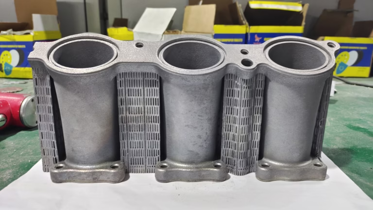
Printing lets you merge parts that would otherwise be bolted together. A motor mount with integrated standoffs, a battery tray with printed clips, or a gear cover with cable routing can all be one solid body. Fewer joints means fewer fasteners, less play, and fewer places for a crash to start a crack.
Consolidation also removes tolerance stacks. Every bolted joint in an RC car adds clearance that shows up as steering slop or drivetrain backlash. A single printed bracket with molded-in bosses holds the mating parts where you modeled them.
There is a limit. A printed hub that carries bearing loads will wear at the bore, and a printed spur gear running against metal will lose teeth. Those parts belong on a machine. Use printing for the geometry around the load path, and machined metal for the surfaces that take the load.
- 1Merge bracketsMotor mount plus standoffs as one printed body.
- 2Cut tolerance stacksFewer joints means less steering and drivetrain play.
- 3Keep metal at the bearingPrinted bores wear fast under rotating load.
When printing is not enough, and CNC takes the load
Printed parts fail in a predictable way: delamination across layers, creep under constant load, and bore wear. If a part sees continuous heat above roughly 80–100 °C, holds a press-fit bearing, or takes repeated shock through a threaded hole, print it in plastic and it will not last a season.
That is where CNC machining complements the printed car. Hubs, differential cases, motor plates, uprights, and shock pivots are small, load-bearing, and need tight fits. Machined 6061-T6 or 7075-T6 holds a bore to ±0.005 mm and keeps thread strength that plastic cannot match.
The practical split: print the body, the trays, the covers, the arms you are still tuning. Machine the rotating and highly loaded joints. A hybrid car is usually lighter and cheaper than an all-machined one, and it survives crashes that would destroy an all-printed build.
For small runs, machining has no tooling cost either. GreatLight runs one prototype or 10,000+ parts with no minimum order, so a machined hub and a printed arm can ship from the same quote.
- 1Print itCovers, trays, ducts, tuning arms, low-load brackets.
- 2Machine itHubs, pivots, motor plates, threaded joints, bearing bores.
- 3Combine bothPrinted body with machined inserts at the load path.
Fits, finishes, and what to specify on a drawing
Printed parts hold roughly ±0.3 mm on a well-tuned FDM machine and tighter on SLS, which is fine for panels and brackets but not for a bearing seat. If a printed part mates with a precision surface, design a machined insert or leave a pocket and bond the metal piece in.
CNC parts from GreatLight hold ±0.005 mm (±0.0002 in) with surface finish from Ra 0.2–0.8 μm on a fine cut to Ra 1.6–3.2 μm as-machined. Anodizing, hardcoat, bead blasting, and laser marking are available for aluminum RC hardware. Minimum laser character height is 1.5 mm, so plan your part numbers accordingly.
Specify the fit, not just the dimension. A bearing bore should state the press or slip fit and the mating part, not only a nominal diameter. That one line on the drawing prevents most rework on small RC components.
- 1Printed toleranceAbout ±0.3 mm; treat as non-critical fits only.
- 2Machined tolerance±0.005 mm with 100% inspection before shipment.
- 3State the fitGive press or slip class, not just a diameter.
Questions engineers ask about printed and machined RC parts
Which RC parts should I print first?
Start with non-critical, easily replaced parts: body panels, battery trays, receiver boxes, antenna mounts, and suspension arms you are still tuning.
Once the geometry is settled and the part survives a few race weekends, decide whether it stays printed or moves to machined aluminum.
Is a printed suspension arm strong enough to race?
In PA12 or PA-CF with the right layer orientation, a printed arm often matches a molded one for a few races. It will not match a machined 7075 arm.
Orient the arm so the main bending load runs along the beads, use at least three perimeters, and inspect the layer lines after every hard hit.
Why do printed parts crack between layers?
Layer adhesion is always weaker than the bead itself. Loads across layer lines pull the part apart.
Rotate the part in the slicer so tension and bending run in the XY plane, raise nozzle temperature slightly, and avoid cooling fans on functional nylon parts.
Can you machine a single replacement hub?
Yes. There is no minimum order quantity, so one prototype and a 10,000+ part run go through the same process.
Quotation and free DFM analysis come back within 12 hours, and production can start within 24 hours. Parts typically ship in 3–5 days.
What materials do you machine for RC hardware?
Aluminum 6061-T6, 2024, 6082, and 7075; stainless 303, 304, 316, and 17-4PH; steel 4130, 4140, and 4340; plus titanium TC4 and brass.
Finishes include clear, color, and hardcoat anodizing, electroless nickel, black oxide, bead blasting, and laser marking.
How do you handle my design files?
Uploads are secure and confidential, and an NDA is available on request.
We run raw material checks, in-process monitoring, and a final inspection before shipment, with reports on request.
Send the CAD file and get a manufacturability read
Upload a printed arm or a machined hub. We return a quote and free DFM analysis within 12 hours, and parts ship in 3–5 days.
12-hour quote100% inspectionNo MOQ









