
7 Critical CNC Metal Lathe Secrets to Raise Turning Efficiency
A practical guide for engineers and buyers who run turned parts in steel, stainless, aluminium, and titanium. It covers the seven levers we adjust first on a critical CNC metal lathe, what each one costs, and when a job should move to a mill-turn or 5-axis platform instead.
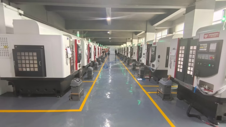
What Actually Moves the Cycle Time
Most turning gains come from four physical things: the cutting edge, the chip, the part holding, and the heat. Everything else is measurement.
Treat the Insert as a System, Not a Line Item
An insert is not a consumable you reorder once a year. Substrate, coating, rake angle, nose radius, and chipbreaker all have to match the material batch in front of you, not the generic grade listed in a catalog. On a critical CNC metal lathe running 316L stainless, an MT-CVD coated carbide insert with a high-positive rake and a nose radius sized to the depth of cut cuts noticeably lighter than a general-purpose steel insert. Lower cutting force means less deflection, steadier dimensions, and slower flank wear.
Read the chip, not the tool catalog. Continuous stringy chips that wrap around the turret tell you the chipbreaker is wrong for that feed and depth. A breaker that curls and snaps the chip inside the evacuation window keeps the turret clear and removes the bird-nest stops that quietly eat an hour per shift. When the chip breaks short and blue at the outside edge, the edge is doing its job.
Keep a simple log per insert grade: material, hardness, surface speed, feed, depth of cut, pieces per edge, and failure mode. After a few jobs the log tells you which grade pays for itself and which one only looks cheaper at the purchasing desk. That record is worth more than any single tooling discount.
Own the Cutting Parameters, Don't Let CAM Decide
CAM libraries ship conservative feeds and speeds because they must work on the weakest machine in the world. Treat them as a starting point. On a rigid lathe with a well-supported part, surface speed and feed per revolution can usually move up before depth of cut does. Raising speed reduces the time the edge spends rubbing; raising depth of cut loads the insert and the spindle more. Test one variable at a time.
A thin-walled aluminium housing shows the pattern. The default suggestion may be 500 m/min and 0.15 mm/rev. Pushing surface speed toward 800 m/min while trimming depth of cut to 0.2 mm often shifts the excitation frequency away from the workpiece natural mode, and chatter drops. The finishing pass then holds size without a second spring pass.
Resonance is measurable. Portable hammer testing and modal checks identify the spindle-workpiece frequencies worth avoiding, and a dry run with audio monitoring confirms it before the first cut. On stable setups we have pushed material removal rates well past textbook values. On long slender shafts, the same push produces taper and chatter. The part decides, not the chart.
Feed per revolution controls chip thickness and surface finish together. Too low a feed rubs and work-hardens stainless. Too high a feed tears soft aluminium and leaves a visible pattern. Find the window per material and write it on the setup sheet.
Plan Workholding Around the Whole Part Cycle
Workholding is usually chosen for the first operation and then inherited by every later one. That is backward. Look at the complete cycle: which face is the datum, where the part is gripped for each op, how much material is removed between grips, and where the part will deflect when the grip releases. A three-jaw chuck that holds a thin ring perfectly on op one may ovalize it on op two because the jaw pressure and the residual stress pull in opposite directions.
For rings, bushings, and flanges, a expanding mandrel or a pie-jaw bored to the actual part diameter spreads the clamping load and keeps roundness. For long shafts, a steady rest placed near the cut reduces the unsupported span and lets you keep feed up without bowing. For a part that needs five faces, an indexer on the lathe can finish more of the cycle without a second setup, which removes one re-fixturing error entirely.
Count the setups on paper before quoting. Each extra setup adds a datum transfer, a possible tolerance stack, and handling time. On a critical CNC metal lathe, one extra op is often more expensive than the cycle time it saves. If the geometry truly needs four or five sides, a mill-turn center or a simultaneous 5-axis machine usually beats adding fixtures to a two-axis lathe.
Grip pressure is a process variable, not a default. Mark the pressure used on the setup sheet, and check roundness after release on the first part of every run.
Coolant and Chip Management as One Decision
Coolant choice and chip evacuation solve the same problem from two directions. High-pressure through-tool coolant reaches the cutting zone under the chip, breaks the thermal cycle that causes built-up edge, and flushes chips away from the insert. Flood coolant on an open setup mostly cools the part after the cut, which is late. For deep holes and grooving in stainless or titanium, through-tool delivery is usually the difference between a stable process and a burned edge.
Match the fluid to the operation. Neat oil suits deep-hole drilling, threading, and hard materials where lubricity matters most. Water-miscible emulsion handles high-volume turning and keeps the part cool. For aluminium, use a fluid and concentration that will not stain the surface, and keep the concentration in range because dilution drifts over a shift.
Chips are a logistics problem as much as a cutting problem. A conveyor sized for the chip volume, a chip breaker that produces short chips, and a coolant stream aimed to carry them out of the way keep the turret clear. Most unplanned stops on a turning cell are chip related, not tool related.
Track coolant concentration weekly. A refractometer reading takes seconds and prevents a slow slide into poor finish, odour, and tool wear.
Use the Data the Lathe Already Produces
A modern turning center reports load, spindle speed, feed override, tool offsets, and alarms. Most shops collect none of it. Recording spindle load per tool and per program gives you an early warning of wear, a material batch change, or a fixture that has shifted. A load trend that rises across a run means the edge is dulling or the chip is not clearing.
In-process gauging and probing close the loop further. Measure a critical diameter in the machine, feed the offset back automatically, and the second and third parts hold size without an operator touching the offset page. For runs above a few hundred pieces, the reduction in scrap alone usually pays for the probe.
Keep it simple at the start. Log spindle load, tool life count, and first-off inspection results for the tools that fail most often. Three numbers per tool are enough to see a pattern. Reporting tools that produce dashboards nobody reads add cost without changing a single decision.
The point is not connectivity for its own sake. It is knowing which tool will fail before it scrapes a batch.
Turning Setup Reference by Material
Typical starting points for stable setups on a rigid lathe. Adjust to the actual part and hardness.
| Material | Insert / Coating | Coolant | Watch For |
|---|---|---|---|
| 6061-T6 aluminium | Polished uncoated, high rake | Emulsion, stain-free | Built-up edge, tearing at low feed |
| 316L stainless | MT-CVD carbide, high positive | Neat oil or HP emulsion | Work hardening, stringy chips |
| 4140 / 4340 steel | CVD carbide, medium chipbreaker | Emulsion, high pressure | Notch wear at depth-of-cut line |
| Ti-6Al-4V | Uncoated or PVD fine grain | High-pressure through-tool | Heat at the edge, chatter on thin walls |
| C36000 brass | Uncoated, sharp edge | Light emulsion or dry | Chip packing in deep grooves |
| 17-4PH (SUS630) | PVD carbide, strong edge | Neat oil preferred | Taper on long shafts, work hardening |
Preventive Precision Beats Preventive Maintenance
Scheduled maintenance keeps a lathe running. Preventive precision keeps it making good parts. The two are not the same checklist. Precision checks include spindle thermal growth at start of shift, turret repeatability, tailstock alignment, and the actual roundness of the first part after a tool change, not just the oil level and filter date.
Thermal drift is the quiet one. A lathe that sits cold overnight grows as the spindle warms, and a diameter that was on size at 07:00 can drift outside tolerance by 09:00. Warm-up cycles, a stable coolant temperature, and a first-article check after warm-up remove most of that variation. Shops that skip the warm-up compensate all morning and wonder why offsets keep moving.
Tool-life limits belong in the program, not in an operator's memory. Set a piece count or a load threshold per tool and change the edge on schedule. A worn edge that still looks acceptable under a light produces rising surface roughness and inconsistent size long before it fails visibly.
Record the first-article result, the offset used, and the ambient temperature. Over a month, that record explains most of the day-to-day variation on the machine.
Choose a Supplier Who Runs the Same Process
The last lever is not on the machine. It is who runs it. Ask a turning supplier three direct questions: which machine and control will run the part, what the first-article and in-process inspection plan is, and what happens when a dimension drifts mid-run. Answers that name a specific process and a specific check are a good sign. Answers that stay general are not.
For a critical CNC metal lathe job, the useful supplier has both turning and milling capacity under one roof, so a mill-turn or 5-axis operation is a routing decision rather than an outsourcing step. GreatLight runs 127 high-precision CNC machines across three wholly-owned plants, including 16 mill-turn centers and 16 simultaneous 5-axis machining centers, with a Ø400 mm rotary table and up to 4,000 mm maximum processing size. Turning, milling, finishing, and inspection stay in one quality system.
Qualification matters more than brochure claims. Working to ISO 9001:2015, IATF 16949:2016, ISO 13485:2016, and ISO 27001:2022 means the inspection records, traceability, and document control are audited. For prototypes, no minimum order quantity applies, and the same process can scale to 10,000+ part runs.
Ask for the inspection report with the parts. If a supplier cannot show raw material check, in-process monitoring, and final inspection results, the tolerance on the drawing is only a hope.
Turning Questions Engineers Ask
Can you hold ±0.005 mm on a turned diameter?
Yes, on rigid setups with a stable material and controlled temperature. The limit is usually the part, not the machine: thin walls, long unsupported shafts, and soft aluminium move under clamping and cutting force.
We confirm the achievable tolerance at the first article and state it on the inspection report rather than assuming the drawing value.
When should a turned part move to a mill-turn or 5-axis machine?
When the part needs features on four or more faces, or when the extra setups on a two-axis lathe would add more tolerance stack than the cycle time saves.
Mill-turn centers finish the back side and cross features in one setup, which removes a datum transfer. For complex geometry, simultaneous 5-axis handles it directly.
How do you control chatter on thin-walled turning?
Reduce radial engagement and raise surface speed to move away from the workpiece natural frequency. Support the wall with a pie-jaw or expanding mandrel, and keep the tool overhang short.
A dry run with audio monitoring confirms the stable window before production starts.
What surface finishes can you achieve on turned surfaces?
As-machined turning typically lands at Ra 1.6–3.2 μm. A controlled finishing pass reaches Ra 0.8–1.6 μm, and fine finishing on suitable materials reaches Ra 0.2–0.8 μm.
The finish depends on material, feed per revolution, and tool condition, so we set it per feature.
What materials do you turn most often?
Aluminium 6061, 6061-T6, 2024, 7075, and 6082; stainless 303, 304, 316, 316L, 17-4PH, and 440C; steel 1018, 1045, 4130, 4140, and 4340; plus titanium TA1, TA2, TC4, Inconel, and copper alloys.
Plastics including POM, PEEK, and PA are also routine.
How do you handle confidential drawings?
Uploads are secure and confidential. We sign an NDA on request before reviewing files, and document control follows ISO 27001:2022 practice.
Quotation and free DFM analysis are returned within 12 hours, and production can start within 24 hours of approval.
Send the Drawing, Get a Turning Plan
Share a print or a STEP file and we will come back with a routing, the critical tolerances, and a first-article inspection plan.
12-hour quote and DFM±0.005 mm tolerance100% inspection before shipmentNo minimum order quantity









