GreatLight CNC Machining Factory logo
CNC Machining
Rapid Prototyping
Materials
Industries
News
About GL

Get Instant Quote

Welded Shafts

Welded Shafts

We join shaft sections and dissimilar metals by friction welding, then machine the assembly to final size. One shop handles the weld, the turning, the heat treat callouts and the inspection report.

Friction weldingDissimilar metalsUp to 4,000 mm±0.005 mmRa 0.8–1.6 μm100% inspection
Leader in Cnc Machining Service China
15 yearsShaft manufacturing since 2011
127High-precision CNC machines
99.99%Qualification rate
4,000 mmMaximum processing size
Where welded shafts go wrong

Four failures we see on incoming drawings

Most of them are decided before the first cut, at the joint.

01

A shaft too long for one bar

Stock over 4,000 mm or a bar size your lathe cannot hold forces a joint. The joint then has to carry the same torque and bending load as the solid section. If nobody sizes it for that, the shaft fails at the weld line, not in the bearing journal where you expected wear.

02

A stainless journal on a carbon steel body

The bearing seat needs corrosion resistance. The rest of the shaft does not. Welding the two by hand brings in filler metal, distortion and a heat affected zone that machines differently on each side. Your finish callout then holds on one side of the joint and drifts on the other.

03

Runout that only shows up after welding

Two straight sections can be straight on their own and still come out of the weld with 0.3 mm of runout. That eats the grinding allowance. You either scrap the part or open the tolerance, and both cost more than the weld did.

04

A weld nobody inspected

A joint that looks clean from outside can carry lack of fusion or porosity inside. On a rotating part under load, that is a crack starter. Without a bond check and a runout check after welding, the first sign of trouble is a field failure.

How we build them

Weld first, then machine to size

The joint is made in one operation, the geometry is cut after, and every assembly is checked against the drawing.

CNC Lathe Technical Specifications Terminology
Joining

Friction welding holds the joint without filler metal

One section spins, the other is pressed against it. Rubbing speed and axial force bring both faces to a plastic state, and the two materials fuse across the full face. No filler wire, no flux, no manual welder judgment on the joint.

That matters for welded shafts because the bond is a full-face forge bond, not a bead laid around a diameter. It handles stainless to carbon steel, 4140 to 1045, and similar combinations where you want corrosion resistance or wear resistance only where it is needed.

Heat stays local to the joint. The rest of the shaft keeps its original properties, so pre-machined journals do not need to be re-cut after welding.

  • 1
    Full-face bondLoad is carried across the whole section, not a bead.
  • 2
    No filler metalOne less material to specify and certify.
  • 3
    Local heatJournal hardness away from the joint is unaffected.

Get Instant Quote

6011
Machining after the weld

Turning the assembly to final size, in one setup where possible

A welded blank is never concentric on its own. We indicate the assembly on the lathe, then cut journals, shoulders, keyways, splines and threads to the drawing. Bearing seats usually land at Ra 0.8–1.6 μm; seal faces get finer.

When the part is long, we machine between centers or use a steady rest so the joint is supported while the journals are cut. The result is total indicated runout measured against the datums on your drawing, not against the weld line.

Mill-turn centers let us cut cross holes, flats and keyways in the same setup as the turning. Fewer setups means fewer datum shifts, and that is where runout usually creeps in.

After machining, the shaft goes to 100% inspection: diameter, runout, surface finish and, where specified, a bond check on the joint.

  • 1
    Indicated on datumsRunout is measured to the drawing, not to the weld.
  • 2
    Between centersLong shafts stay supported during journal cutting.
  • 3
    Mill-turnCross features cut without a second setup.

Get Instant Quote

Choosing a joint

Which joining method fits your shaft

Match the method to the load path, the materials and the section size.

MethodBest forWatch out for
Friction weldingSolid round sections, dissimilar metalsNeeds a round face and axial force
Machined from solidShort shafts, tight runoutBar size and stock cost
TIG or MIG weldingOdd shapes, low-speed partsDistortion, filler metal, HAZ
Shrink fit or press fitTemporary or serviceable jointsSlip under reversing torque
Spline or keyed jointTorque transfer, serviceableBacklash and added length
What we do around the weld

Shaft work under one roof

One supplier for the joint, the geometry, the finish and the paperwork.

01

CNC turning

Journals, shoulders, threads and grooves cut to ±0.005 mm. Long parts run between centers.

02

Milling and mill-turn

Keyways, flats, cross holes and splines cut in the same setup as the turning.

03

5-axis machining

Angled holes and compound features on shaft ends and flanges. 16 simultaneous 5-axis centers.

04

Gear and spline cutting

Involute splines and gear teeth on the same shaft, timed to the journals.

05

Surface finishing

Hard chrome, electroless nickel, black oxide, anodizing, polishing and bead blasting.

06

Inspection and reports

100% inspection before shipment. Material certs and dimensional reports on request.

Capability range

What we can hold on a welded shaft

ParameterRangeNotes
DiameterØ3 mm to Ø400 mmLarger on request
LengthUp to 4,000 mmLonger parts in sections
Tolerance±0.005 mmOn turned features
Runout after weld0.03 mm TIR typicalHolds on most bearing fits
Surface finishRa 0.2–3.2 μmRa 0.8–1.6 μm on bearing seats
Joint typeFriction weldSolid round sections
MaterialsCarbon steel, stainless, 4140, 17-4PHMixed joints supported
Lot size1 piece to 10,000+No minimum order quantity
Why engineers send us the drawing

Numbers, not adjectives

15Y

Shaft work since 2011

Welded, splined, gear, motor and worm shafts are a standing part of our work, not a favor.

±0.005

Tolerances held after welding

Tight enough for bearing seats and seal journals on a welded assembly.

4,000

Maximum processing size

Long shafts and multi-section welded assemblies on machines sized for them.

12h

Quote and DFM analysis

We flag joint location, datums and finish callouts before you commit to tooling.

100%

Inspection before shipment

Dimensional and runout checks on every shaft. Reports supplied on request.

1–10,000+

No minimum order quantity

One prototype or a production run. Same process, same inspection.

7,600 m²Manufacturing space
150Technicians
3Wholly-owned plants
< 2%Historical late-delivery risk
Industries we serve

What those industries require, and what we deliver

CNC Machining Services Online

Automotive & EV rotor shafts

Welded shaft sections for motor and driveline parts, machined to the bearing fit after joining.

  • ±0.005 mm tolerance
  • IATF 16949:2016
  • 100% inspection
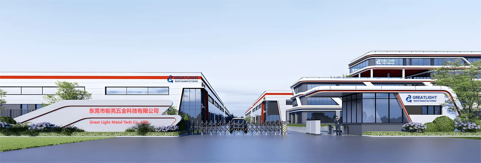
GreatLight Metal new factory building

Industrial machinery drive shafts

Long welded shafts with keyways and splines, cut between centers to hold runout.

  • Up to 4,000 mm
  • 0.03 mm TIR typical
  • Ra 0.8–1.6 μm
oplus_262178

Pump and compressor shafts

Stainless journals friction welded to carbon steel bodies, where only the seal area needs corrosion resistance.

  • Dissimilar metals
  • ISO 9001:2015
  • Material certs
CNC Machining Services Comparison 2026 Fictiv vs Xometry vs GreatLight

Medical device shafts

Small welded assemblies finished to fine surface requirements, with documentation to match.

  • Ra 0.2–0.8 μm
  • ISO 13485:2016
  • Inspection reports
FAQs

Welded shaft questions we get every week

When should a shaft be welded instead of machined from one bar?

When the finished length exceeds what a single bar or machine can handle, or when the two ends need different materials. A pump shaft with a stainless seal journal and a carbon steel body is the common case.

If the part fits inside one bar and one material works, machining from solid removes the joint and the risk that comes with it. We will tell you which one is cheaper on your drawing.

Which material combinations can be friction welded?

Carbon steel to stainless, 4140 to 1045, 17-4PH to 304, and similar pairs where both are forgeable. We work with the aluminum, stainless, steel, copper and titanium grades listed in our material range.

Combinations with very different melting points or a brittle intermetallic layer at the interface need a closer look. Send the pair and we will say yes or no before quoting.

Where should the joint sit on the shaft?

Away from the highest bending moment and away from bearing seats and seal journals. The middle of a simply supported span is the worst place for a joint under bending.

Put it where the diameter is larger and the stress is lower. If the joint has to sit in a loaded zone, we size the section for it and check the weld after machining.

What runout can you hold on a welded shaft?

About 0.03 mm TIR is typical after welding and machining, measured against the datums on your drawing. Tighter is possible on shorter parts or when the journals are ground after welding.

Runout depends on how the assembly is indicated on the lathe. Tell us which surfaces are the datums and we will set up to those.

Do you check the weld itself?

Yes. We check the bond and the runout after joining, before finish machining. If a joint does not pass, we stop and tell you rather than cut the whole part and find out at final inspection.

Dimensional and runout reports go out with the parts on request, along with material certificates.

Can you heat treat or surface finish after welding?

Yes, but the order matters. Stress relief after welding and before finish machining reduces movement during turning. Hardening is usually done before final grinding so the hardness does not fight the cutter.

Electroless nickel, hard chrome, black oxide, anodizing and polishing are all available. Masking at the joint is decided per part.

What is the smallest and largest welded shaft you take?

From Ø3 mm up to Ø400 mm in diameter, and up to 4,000 mm in length. Below Ø3 mm the joint is hard to control; above Ø400 mm we would quote it as a special.

There is no minimum order quantity. One prototype and a 10,000-piece run go through the same process.

How fast can I get a quote and parts?

Quotation and free DFM analysis within 12 hours. Production can start within 24 hours of a released drawing, and parts ship in 3–5 days.

On welded shafts, the answer usually comes back with a note on joint location, datum choice or where the finish callout will be hard to hold. Better to hear it before the steel is cut.

Send the drawing, get a joint plan back

Tell us the load, the materials and the datums. We will come back with a weld-and-machine plan, a price and a DFM note on anything that will be hard to hold.

12-hour quote100% inspectionNo minimum order quantity

Trusted by engineers and manufacturers worldwide

Tesla Ford Motor Company BYD Auto Denso Magna International Boeing Airbus Medtronic KUKA FANUC