
What Is Axis CNC Machine? A Complete Guide
An axis cnc machine moves the tool or the workpiece along controlled directions, and the count of those directions decides what geometry you can cut in one setup. This guide explains the axes, their travel limits, and how to tell whether a part belongs on a 3-axis, 4-axis or 5-axis machine.
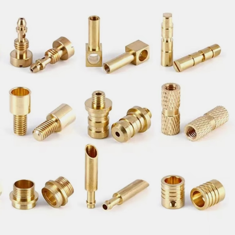
What an axis actually controls
On a CNC machine, an axis is one direction of relative motion between the cutting tool and the workpiece. The controller reads a program, sends commands to servo motors, and each motor drives a slide or a rotary table to a commanded position. The number of axes is simply the number of motions that can be coordinated at the same time.
Linear axes follow the right-hand rule. X runs left to right along the longest bed direction, Y runs front to back, and Z runs up and down, which sets depth of cut. A fourth linear axis is possible on some machines, but on most production floor equipment the fourth axis is rotary, not linear.
Rotary axes are named by the axis they rotate around. A rotates around X, B around Y, and C around Z. When you see a machine listed as 4-axis, it usually means X, Y and Z plus one rotary table. When you see 5-axis, it means three linear axes plus two rotary axes turning at the same time.
The word simultaneous matters. A machine can have four axes but only move three at once. A true simultaneous 5-axis center moves all five under one interpolation block. That is what lets the tool tip follow a compound curve instead of a series of straight segments.
- 1Linear axesX, Y, Z slides. Set position and feed rate.
- 2Rotary axesA, B, C tables or heads. Set angle and angular feed.
- 3SimultaneousAll axes move under one coordinated command.
3-axis, 4-axis and 5-axis configurations
A 3-axis machine moves only X, Y and Z. The tool always points straight down at the part. This is the workhorse for prismatic parts: plates, brackets, housings with features on one face, and simple molds. Setup is fast, programming is straightforward, and the rigid column structure holds tight tolerances well. We run 27 three-axis machines for exactly this kind of work.
A 4-axis machine adds one rotary axis, most often an A-axis trunnion or a C-axis table. The part can index to a new face without being unclamped, so you cut four sides in one setup. Think camshafts, helical gears, splined shafts, and cylindrical engraving. The rotary table on our 4-axis mills is Ø400 mm, which suits shafts and round housings up to that swing.
A 5-axis machine adds a second rotary axis. The two rotations tilt and swivel the tool or the part, so the cutter can approach from almost any direction. This is the only practical way to machine undercuts, deep pockets with drafted walls, and impellers or bladed disks that have no clear top-down access. Our shop runs 16 simultaneous 5-axis machining centers.
Adding axes is not free. A 5-axis program takes longer to prove out, the machine needs more clearance around the part, and the rotary axes have their own positioning error. If a part can be cut in three setups on a 3-axis machine without losing tolerance, that is often the cheaper route.
Travel envelope and part size limits
Axis count is only half the story. Each machine has a travel envelope, the box of space the tool can reach. A 5-axis center with a small envelope cannot cut a large part no matter how many axes it has. The envelope and the axis count together decide whether a part fits.
Our largest platform reaches 4,000 × 400 × 150 mm for long, slender parts like structural rails and extrusions. Medium frames cover 750 × 1,150 × 550 mm and 600 × 600 × 600 mm. Compact frames run 500 × 500 × 450 mm and 500 × 310 × 200 mm for small, high-detail work.
The rotary table adds its own limit. A Ø400 mm table swings a part of roughly that diameter, and the part must clear the table surface and the tool holder through the full tilt range. Long parts on a 4-axis machine need a tailstock or a steady, which eats into the usable length.
Before quoting, we check three things: does the part fit the envelope, can the tool reach every feature without collision, and does the fixturing hold the part rigid enough for the required finish. A part that fits on paper but vibrates in the cut will not hold Ra 0.8–1.6 μm.
How axis count affects accuracy and cost
Every axis adds a stack of error. On a 3-axis machine the error comes mostly from the slides and the spindle. Add a rotary axis and you add its backlash, its runout, and the error of the workholding on top of it. Add a second rotary axis and the errors compound through the kinematic chain.
That does not mean 5-axis is less accurate. It means the machine has to be built and calibrated to hold the same tolerance with more error sources. A well-built 5-axis center holds ±0.005 mm. A worn or poorly set up one will not, even though the spec sheet says it should.
Cost moves the other way. Fewer axes means fewer setups, shorter programs and less fixturing, which lowers the hourly rate and the risk of a scrapped part. More axes means fewer setups but a higher machine rate and longer prove-out. For a 10-part run the 3-axis route often wins. For a 500-part run with complex geometry, the 5-axis route can win on total cost.
The counterintuitive part: a 5-axis machine can be cheaper for a simple part if it eliminates three setups and three fixtures. We quote both routes when the geometry is borderline and let the numbers decide.
Materials and finishes across axis types
Axis count does not limit the material. We cut aluminium 6061, 7075 and ADC12, stainless 303, 304, 316L and 17-4PH, steels 1018, 4140 and 4340, titanium TC4, Inconel, and plastics from POM to PEEK. The choice of axis is driven by geometry, not by the workpiece material.
Material does change the cutting parameters. Aluminium runs fast with high rake angles and generous coolant. Titanium and Inconel run slow, with rigid setups and low radial engagement, because the heat stays in the cut. On a 5-axis machine, a flexible setup in titanium will chatter before it holds tolerance.
Finishes follow the same logic. As-machined surfaces sit around Ra 1.6–3.2 μm. A careful pass with a small stepover can reach Ra 0.8–1.6 μm, and polishing or fine finishing reaches Ra 0.2–0.8 μm. On 5-axis parts, the finish depends more on tool path strategy and stepover than on the axis count itself.
Secondary operations are independent of the machining axes. We offer anodizing in clear, color, hardcoat and conductive, plating in electroless nickel, zinc, silver and gold, powder coating, black oxide, bead blasting and laser marking with a minimum character height of 1.5 mm.
Choosing an axis configuration
Match the part geometry to the machine. When two rows both fit, pick the simpler machine.
| Part feature | Best fit | Why |
|---|---|---|
| Flat plate, holes on one face | 3-axis | One setup, no rotary error |
| Bracket with features on 5 sides | 4-axis | Index between faces, one clamp |
| Shaft with cross holes | 4-axis | Rotary table indexes around the axis |
| Impeller or bladed disk | 5-axis | Tool reaches between blades |
| Deep pocket with drafted walls | 5-axis | Tilted tool clears the wall |
| Large rail, 4,000 mm long | 3-axis | Long travel beats axis count |
| Prototype, tight schedule | 3-axis first | Faster programming and setup |
Which axis configuration fits your part
If the part has features on one face and fits the travel envelope, use a 3-axis machine and save the setup cost. If it needs multiple faces or a rotational feature, use 4-axis. Go to 5-axis only when the geometry has no clear top-down access or when removing setups cuts total cost on a larger run.
Frequently asked questions
Can a 3-axis machine cut a part with features on four sides?
Yes, but each face needs its own setup. The part is unclamped, rotated and re-fixtured, and every new setup adds alignment error.
If the tolerance is loose and the quantity is small, that is fine. If the faces must line up within ±0.005 mm, a 4-axis machine holds the relationship better because the part stays clamped.
Is 5-axis always more accurate than 3-axis?
No. A 5-axis machine has more error sources in its kinematic chain, so it must be built and calibrated more carefully to reach the same tolerance.
Its advantage is reach and setup reduction, not raw accuracy. For a simple part, a rigid 3-axis machine can hold tighter numbers more easily.
How do I know if my part needs 5-axis?
Look for features the tool cannot reach from above: undercuts, deep pockets with drafted walls, curved surfaces that wrap around the part, and blades or impellers.
If a straight tool from any single direction can reach every surface, you probably do not need 5-axis.
What is the largest part you can machine?
Our largest platform reaches 4,000 × 400 × 150 mm. Medium frames cover 750 × 1,150 × 550 mm and 600 × 600 × 600 mm, and compact frames run 500 × 500 × 450 mm and 500 × 310 × 200 mm.
Send the model and we will confirm fit and fixturing before quoting.
Does the axis count change the lead time?
Programming and prove-out take longer on 4-axis and 5-axis work, mainly because the tool path and fixturing need more checking.
Quotation and free DFM analysis come back within 12 hours, production can start within 24 hours, and parts ship in 3–5 days once the process is proven.
Can you add a fourth axis to an existing machine?
It depends on the controller, the drive capacity and the mechanical interface. Some mills accept a bolt-on rotary table; others need a controller upgrade.
The bigger question is whether the part justifies it. If a few parts need a fourth axis, outsourcing to a shop that already runs one is usually faster.
Send your model, get an axis recommendation
Upload your CAD file and we will tell you which axis configuration fits, what tolerance we can hold, and what the part will cost. No minimum order quantity, from one prototype to 10,000+ part runs.
12-hour quoteFree DFM analysis100% inspectionNDA on request
More from GreatLight
We publish setup notes, tooling trials and inspection data from the factory floor.











