
What Is Small Spot Tool CNC Machining?
It is milling and drilling with very small diameter cutters, usually under 1 mm, to produce micro-holes, thin walls and fine grooves. This page explains the mechanics, the boundary conditions and the part features where the process pays off, so you can judge whether your design needs it.
In this article
- 1
- 2
- 3
- 4
- 5
- 6
Definition and working principle
Small spot tool CNC machining is the use of cutting tools with a very small diameter, typically Ø0.1 mm to Ø1 mm, to remove material from a workpiece. The name comes from the small contact spot between the tool tip and the material at any moment. Because that contact area is tiny, the tool can enter a corner, a slot or a hole that a Ø6 mm end mill can never reach.
The cutting mechanics change at this scale. A micro end mill has a core diameter much smaller than its cutting diameter, so it bends easily. Chip thickness per tooth drops into the micron range, and if the tool rubs instead of cutting, the edge dulls within minutes. The usual answer is high spindle speed with a low feed per tooth, so each edge takes a clean bite and leaves the cut before heat builds.
Rigidity matters more than raw spindle power here. A 40,000 rpm spindle on a machine with worn guideways will chatter long before it breaks a tool. Thermal stability matters too. A room that swings 3 °C across a shift moves the part by more than the tolerance band on a 200 mm feature.
So the process is not simply standard milling with smaller cutters. It is a separate discipline with its own tool holding, its own feeds and speeds, and its own inspection routine. Treat it that way and micro features come out repeatable.
Core characteristics that separate it from standard milling
Tool diameter sets the reachable geometry. Below Ø1 mm, the flute length is short and the shank is fragile, so depth of cut is limited. A common rule is to keep axial depth under one tool diameter and radial engagement under 10 percent of the diameter on hard materials. That keeps deflection inside a few microns.
Thin walls behave differently from thin floors. A 0.05 mm wall can be cut, but only if the tool path supports both sides and the finishing pass removes equal stock. Climb milling on the final pass reduces the burr and lowers side load.
Heat has nowhere to go on a micro tool. The chip carries most of the heat away when the feed per tooth is correct. When it is too low, the edge rubs and the coating fails. Coolant choice follows the material: air blast or minimum quantity lubrication on plastics, flood coolant on stainless and titanium.
Surface finish is a function of tool runout, not just feed. A holder with 3 μm runout will leave a visible pattern at Ra 0.8–1.6 μm, while a shrink-fit or hydraulic holder at 1 μm runout can reach Ra 0.2–0.8 μm on aluminium with the same parameters.
Materials and the limits each one imposes
Aluminium is the easiest family for this process. Grades 6061, 7075 and 6082 cut cleanly at high spindle speed, and a two-flute micro end mill can hold Ra 0.8–1.6 μm without polishing. Watch built-up edge on soft 5052; a small increase in feed per tooth usually clears it.
Stainless steel 303 and 304 work well with sharp uncoated carbide and flood coolant. Grades 316L and 17-4PH work-harden quickly, so never dwell in the cut. Keep the tool moving and avoid a spring pass.
Titanium TC4 (Ti-6Al-4V) and Inconel are possible at small diameter, but tool life drops sharply. Expect to change micro tools more often, and plan a separate roughing strategy with a larger cutter wherever the geometry allows.
Plastics and composites need their own settings. PEEK and POM cut cleanly with sharp single-flute tools and air blast. Carbon fibre abrades the edge fast, so diamond coating is worth the cost. Ceramic is machinable but fragile; support the part and keep radial engagement low.
How the process is planned and controlled
Planning starts with the smallest feature on the drawing. That feature sets the tool list, and the tool list sets the machine. If the smallest hole is Ø0.3 mm and it sits 40 mm deep inside a pocket, the reach becomes the problem, not the diameter.
Tool holding is the next constraint. Shrink-fit and hydraulic holders give the lowest runout, but they are limited in the small sizes available. High-precision collet chucks work down to Ø1 mm with runout around 3 μm. Below that, dedicated micro chucks are the practical choice.
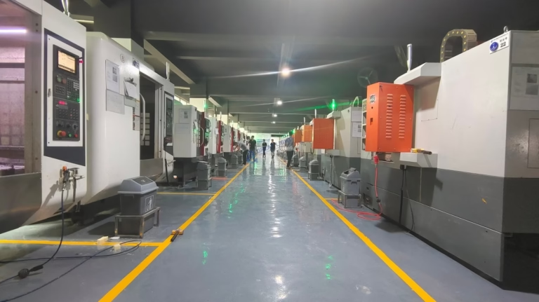
Machines need high spindle speed and fine resolution on the feed axes. A machine with 0.1 μm positioning resolution and a thermally stable frame holds the tolerance. In our shop, 16 simultaneous 5-axis centers, 12 four-axis mills and 27 three-axis machines cover the range from Ø0.1 mm micro work up to a 4,000 mm maximum processing size.
Inspection closes the loop. Micro features cannot be checked with calipers. We use optical measurement and, where needed, CT scanning for internal channels. Every part gets 100% inspection before shipment, with reports on request.
Common failure modes and how to avoid them
Tool breakage is the most visible failure. It usually comes from chip packing in a narrow slot, not from the feed rate. Widen the slot by 5 percent of the tool diameter, use a trochoidal path and add through-spindle air if the machine supports it.
Vibration and deflection show up as a taper on a wall or a shiny band at the bottom of a pocket. Reduce axial depth, shorten the gauge length and check runout before blaming the program. A holder swap often fixes what a parameter change cannot.
Heat buildup shows as discoloration on stainless or a melted burr on plastic. Increase feed per tooth, raise coolant pressure and reduce the number of finishing passes. On aluminium, a small amount of lubricant in the air blast is often enough.
Batch consistency is the quiet risk. Tool wear across 2,000 parts moves the effective diameter by several microns. In-process probing and scheduled tool changes keep the spread inside the tolerance band. Our historical qualification rate on this class of work is 99.99%.
When small spot tool CNC machining fits and when it does not
Use this as a first filter before you send a drawing.
| Part feature | Small spot tool | Standard CNC |
|---|---|---|
| Micro-hole under Ø0.5 mm | Yes, drilled or milled | No, drill too large |
| Wall thickness 0.05–0.2 mm | Yes, with support paths | Risks deflection and chatter |
| Deep pocket, depth over 5× tool Ø | Difficult, needs step-downs | Yes, rigid tool |
| Fine text or texture, Ra under 1 μm | Yes, with low runout holder | Limited, needs polishing |
| Feature size above 3 mm | Possible but slow | Yes, faster and cheaper |
| Hardened steel over 50 HRC | Limited, tool wear high | Yes, with carbide or CBN |
| Production volume over 10,000 parts | Possible, watch tool cost | Usually better per part |
| Batch of one prototype | Yes, no tooling needed | Yes, no tooling needed |
Where this process makes sense
If your smallest feature is under Ø1 mm, or a wall is thinner than 0.2 mm, small spot tool CNC machining is the right route and standard milling will not hold it. If the smallest feature is above 3 mm and the volume is high, standard CNC with larger cutters is faster and cheaper per part. Choose by feature size first, then by volume.
Frequently asked questions
What is the smallest tool diameter you use for small spot tool CNC machining?
We routinely run micro end mills at Ø0.1 mm and above. Below that, tool life and reach become the limiting factors rather than the machine. If your feature needs something smaller, send the drawing and we will confirm whether it is practical.
Which materials can be machined this way?
Aluminium 6061, 7075 and 6082, stainless 303, 304, 316L and 17-4PH, titanium TC4, Inconel, copper alloys, and engineering plastics such as PEEK, POM, PA and PC. Carbon fibre is also possible with diamond-coated tooling.
Each material needs its own speeds, feeds and coolant strategy, so the material callout on the drawing matters as much as the tolerance.
How do you hold ±0.005 mm across a full production run?
We control three things: thermal stability in the room, tool runout on every holder, and scheduled tool changes based on measured wear. In-process probing catches drift before the part leaves the tolerance band. Final inspection is 100 percent before shipment.
What post-processing is available after micro machining?
Anodizing in clear, colour, hardcoat and conductive types, electroless nickel, zinc, silver and gold plating, powder coating, black oxide, bead blasting, tumbling, brushing and polishing. Laser marking is available down to 1.5 mm character height.
Do you take projects with no minimum order quantity?
Yes. We run from a single prototype up to 10,000+ part runs. Quotation and free DFM analysis come back within 12 hours, and production can start within 24 hours of approval. Standard parts ship in 3–5 days.
Can you review a design before we commit to tooling?
Yes. Upload the model and we will flag features that are too thin, too deep or too small for the tolerance called out. An NDA is available on request if the design is not public.
Send your micro features for a DFM review
Upload the model and we will tell you which features need small spot tool CNC machining and which do not.
12-hour quote100% inspectionNo minimum order
More from GreatLight
We publish setup notes, tooling trials and inspection data from the factory floor.











