
What Is the Z Axis in a CNC Machine?
The z axis in cnc machine motion moves the spindle or table along the tool axis, which sets depth of cut, hole depth and the top face of every pocket. This page explains how that motion is built, where it is referenced from, and when a 3-axis Z range stops being enough for a part. Written for engineers and buyers who need to judge setups, not memorize definitions.
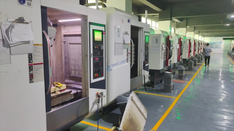
How the Z Axis in CNC Machine Work Is Defined
In a standard 3-axis mill, the z axis in cnc machine control runs parallel to the spindle centerline. X and Y move the part or the tool across the table. Z moves along the tool axis, so it is the axis that decides how far the cutter enters the material. Feed into a pocket, peck into a hole, or face the top of a block, and the Z axis is doing the work.
On a vertical machining center the Z slide usually carries the spindle head. On a gantry mill it may carry the whole bridge. Either way, the mechanical job is the same: convert servo rotation into straight-line motion with minimal backlash. A worn Z ball screw shows up as inconsistent depth, not as a visible wobble.
Every cut needs a Z reference. Programmers set the work offset so Z0 sits on a known surface, often the top of the stock or a datum face. Touch off 0.05 mm too high and every pocket comes out shallow; 0.05 mm too low and the first pass buries the tool. That is why Z setting gets checked twice on tight-tolerance jobs.
- 1Vertical millSpindle head moves along Z; table holds X and Y.
- 2Gantry millZ slide hangs from a moving bridge, common on long parts.
- 3LatheZ follows the bed axis; X sets diameter.
What the Z Axis Controls During a Cut
Depth of cut belongs to Z. A 12 mm end mill taking 0.5 mm radial and 6 mm axial is a Z decision as much as a feed decision. Push axial depth too far on a long tool and the cutter deflects, leaving a tapered wall. Pull it back and you trade cycle time for dimensional stability.
Hole depth is another Z number. A Ø8 mm drill going 30 mm deep needs peck cycles, and each retract is a Z move. Chip evacuation depends on those retracts. Skip them in 6061 aluminium and you may get away with it; try the same on 316 stainless and the drill will rub and work-harden.
Tool length offsets live in Z too. Every tool in the carousel has its own offset, measured or probed. One wrong offset and the tool either air-cuts or crashes. This is the single most common 3-axis error we see on incoming programs.
- 1Axial depthSets tool load and wall straightness.
- 2Peck depthControls chip clearing in deep holes.
- 3Tool offsetDefines where each tool tip actually is.
How the Z Axis Changes on 4-Axis and 5-Axis Machines
A 4-axis mill adds a rotary table, usually turning around X or Y. The Z axis still points along the spindle, but now it can reach features on a cylinder because the part rotates underneath it. Think cam profiles, shaft flats and cross-drilled holes done in one setup.
A 5-axis machine adds a second rotary. The tool can tilt, so Z is no longer locked to one direction in part space. This is what lets a ball nose cutter stay normal to a curved surface. It also means the control must blend five motions at once, which is where surface finish is won or lost.
On our 16 simultaneous 5-axis centers, tilting the tool often removes the need for long reach. A stubby cutter held at 30° reaches a deep rib with far less deflection than a long tool going straight down. That is a Z-range problem solved by geometry rather than by a bigger machine.
- 13-axisZ is fixed to the spindle; part stays put.
- 24-axisZ plus one rotary; good for cylindrical parts.
- 35-axisZ tilts with the tool; complex surfaces in one setup.
Where a 3-Axis Z Range Stops Working
Z travel is finite. Our large-format machines run 4,000 × 400 × 150 mm, medium frames cover 750 × 1,150 × 550 mm and 600 × 600 × 600 mm, and compact frames sit at 500 × 500 × 450 mm or 500 × 310 × 200 mm. A part taller than the Z stroke cannot be finished in one setup, no matter how good the program is.
Reach is the other wall. A deep cavity in a tall block needs a long tool, and long tools chatter. Once length-to-diameter passes roughly 4:1 in steel, finish and tolerance both suffer. At that point you either tilt the part, flip it, or move to a machine with a rotary table.
Undercuts and side features are the third limit. A straight Z move cannot reach a groove on the side wall of a pocket. If the drawing has such a feature, plan a second setup or quote it on a 5-axis center from the start.
- 1Too tallPart exceeds Z stroke; split the setup.
- 2Too deepLong tool deflects; tilt or use 5-axis.
- 3UndercutStraight Z cannot reach; needs rotation.
How Z Accuracy Shows Up in the Finished Part
Z errors are usually dimensional, not visual. A 0.02 mm depth error on a bearing seat is a press-fit problem. The part still looks fine. That is why Z-related checks focus on depth, step height and flatness rather than on surface appearance.
Thermal growth matters on long cycles. A spindle that warms by a few degrees shifts Z by microns over an hour of roughing. On jobs held to ±0.005 mm, we rough, let the machine settle, then finish. Skipping that pause is a common cause of drift between the first and last part in a batch.
We check 100% of parts before shipment, with raw material checks, in-process monitoring and a final inspection. Reports are available on request. On Z-critical features the report typically lists measured depth and step height against the drawing callout.
- 1DepthMost common Z-driven reject.
- 2Step heightReveals tool offset drift.
- 3FlatnessSensitive to spindle tilt and heat.
Z Axis Behavior by Machine Type
Use this when deciding which machine a part should be quoted on.
| Machine type | Z motion | Best for | Main limit |
|---|---|---|---|
| 3-axis vertical | Spindle head moves on Z | Prismatic parts, plates, simple pockets | No side access, one face per setup |
| 4-axis with rotary | Z fixed, part rotates | Shafts, cams, cross-drilled holes | Rotary axis adds one more direction |
| 5-axis simultaneous | Z tilts with the tool | Curved surfaces, deep ribs, undercuts | Higher programming and setup cost |
| Gantry mill | Z hangs from moving bridge | Long parts up to 4,000 mm | Large footprint, slower on small parts |
When to Stay 3-Axis and When to Move Up
If every feature is reachable from the top or from a few flips, stay 3-axis: it is cheaper and faster to program. If the part has undercuts, deep ribs, or curved faces that need the tool normal to the surface, quote it on a 5-axis center from the start.
Frequently Asked Questions
Is the Z axis always vertical?
On most vertical machining centers, yes. The Z axis runs parallel to the spindle, which points down at the table.
On horizontal mills and lathes the same axis name follows the spindle or bed instead, so Z can be horizontal. Always read the machine configuration before assuming a direction.
What happens if the Z offset is wrong?
A high offset air-cuts and leaves a shallow feature. A low offset drives the tool deeper than programmed and can break it or scrap the part.
On tight jobs we probe or touch off Z twice, once at setup and once before the finishing pass.
How deep can a 3-axis machine cut in one Z pass?
It depends on the tool and material, not on the machine alone. A Ø12 mm carbide end mill in 6061 aluminium can take 6–8 mm axial depth at moderate feed.
In 316 stainless the same cutter is safer at 2–3 mm. Past that, deflection shows up as taper in the wall.
Does the Z axis affect surface finish?
Yes, mainly through tool length and rigidity. A long Z extension flexes, and the cutter leaves marks that no feed change will remove.
Shortening the tool, tilting the part, or moving to a 5-axis setup usually fixes finish problems that come from Z reach.
Can Z travel be extended?
Only within the machine frame. You can add riser blocks on some vertical mills, but stiffness drops and accuracy follows.
For parts taller than the Z stroke, splitting the setup or using a gantry machine with a 4,000 mm envelope is the practical answer.
Send Us the Drawing, We Will Check the Z Setup
Upload a STEP file and we will return a quote plus a free DFM analysis within 12 hours, including a note on whether the part suits 3-axis, 4-axis or 5-axis work.
12-hour quote100% inspectionNo minimum order quantity
More CNC Machining Notes
We publish setup notes, tooling trials and inspection data from the factory floor.











