
Sheet Metal CNC Costs Too High? 7 Pro Tips to Slash Them Now
Most of the money in a sheet metal part is decided before a machine ever moves. This guide walks through seven changes engineers can make in CAD, material callouts and finishing specs to bring sheet metal CNC costs down without losing function. Each tip lists what to change, the parameter ranges that work, and where the approach stops paying off.
In this article
- 1
- 2
- 3
- 4
- 5
- 6
- 7
- 8
Key takeaways
Bake DFM into the CAD before the first quote
Sheet metal CNC costs are largely locked in by the time a drawing reaches a supplier. Laser cutting, punching, bending and tapping each react to geometry in a predictable way, and the quoting engineer sees those reactions as line items. If the model has a 0.5 mm inside bend radius on 3 mm cold-rolled steel, the shop either quotes a relief cut or quotes a crack risk. Neither is cheap.
The single highest-return habit is to run a design-for-manufacturing pass before release. Check four things: inside bend radius against thickness, hole-to-bend distance, slot width against sheet thickness, and whether any feature needs a secondary operation that could be designed away. On 1.5–3 mm sheet, an inside radius of 1× thickness is a safe default for mild steel and aluminum; 304 and 316 stainless usually want 1.5× to 2× thickness to avoid orange peeling on the outside of the bend.
Hole placement matters just as much. Keep holes and slots at least 2.5× material thickness plus the bend radius away from a bend line, otherwise the hole distorts and the part gets scrapped. Slots narrower than 1× thickness on a laser are slow and dross-prone; widening a 1.2 mm slot to 2 mm on 2 mm sheet often removes a deburring step entirely.
Symmetry is free money. A symmetrical bracket nests at high material utilization because the blank can be mirrored across the sheet. Irregular, one-sided shapes leave a lot of skeleton. If a part is nearly symmetric, ask whether the last asymmetric feature is functional or just inherited from an older revision.
- 1Check before releaseBend radius, hole-to-bend distance, slot width, secondary ops.
- 2Radius rule of thumb1× thickness for steel and aluminum, 1.5–2× for 304/316.
- 3Hole clearance2.5× thickness plus bend radius from the bend line.
Pick the material and gauge the load actually needs
Material is usually the largest single line on a sheet metal quote, so it is also the easiest place to overspend. Engineers often carry a material spec forward from an earlier program without re-checking the load case. A camera bracket that weighs 0.5 kg does not need 3 mm 316 stainless if 1.5 mm galvanized steel passes the vibration and corrosion requirements.
Work through three questions in order. What is the actual load and stiffness requirement? What environment will the part see (indoor, salt spray, washdown, temperature swing)? Does the surface finish process constrain the alloy? Answering those three usually narrows the choice to one or two alloys, and the cheaper one is frequently acceptable.
Gauge tables are a common source of confusion because the same gauge number means different thicknesses in different standards. When a drawing says 14 ga, confirm whether that is 1.9 mm (mild steel) or 2.0 mm (aluminum). Mixed gauges in one assembly also force separate setups and separate nests. Standardizing on one or two thicknesses across a product family reduces both material variety and machine time.
Aluminum 5052 bends well and resists corrosion, which makes it a good default for enclosures. 6061 machines and welds cleanly but cracks at tight bend radii in the T6 condition. 304 stainless is the workhorse for food and medical equipment; step up to 316 or 316L only when chloride exposure is real.
- 1Start from the loadConfirm stiffness and environment before naming an alloy.
- 2Check the gauge standard14 ga differs between steel and aluminum tables.
- 3Standardize thicknessFewer gauges means fewer nests and fewer setups.
Merge parts and cut the number of setups
Every setup carries a fixture, a program, a first-article check and a handling step. On low-volume work those fixed costs can exceed the cutting time. If a product uses a left bracket and a right bracket that differ by one hole, ask whether a single symmetric part with two hole patterns would work. One part number means one setup, one nest and one inspection.
Welded assemblies are another place where part count hides cost. Five small plates welded into a frame need five cutting programs, a fixture, weld time, straightening and re-inspection. A single machined or folded part can replace the whole stack if the geometry allows. The trade-off is real: a large folded part may need a bigger press brake and a longer bend sequence, so compare total cost, not just cutting cost.
Hardware insertion is worth reviewing too. Pressed-in standoffs, rivet nuts and clinch studs each add a station and a failure mode. Where the load allows, a formed tab or an extruded hole can do the same job with no purchased hardware. Keep the added hardware only where serviceability or thread strength demands it.
The practical rule: count the operations on the routing, not the parts on the drawing. If two parts share a material, a thickness and a finish, they are candidates to merge. If merging forces a tolerance stack that cannot hold, keep them separate and accept the setup cost.
- 1Mirror partsLeft and right brackets with one hole difference can become one part.
- 2Replace weldmentsA single folded part can remove a fixture, weld and straighten cycle.
- 3Review hardwareFormed tabs and extruded holes avoid purchased inserts.
Cut secondary operations and over-specified finishing
Secondary operations are where sheet metal CNC costs quietly accumulate. Deburring, countersinking, tapping and reaming are each quoted separately. A laser-cut edge on 2 mm mild steel usually needs a light tumble; the same edge on 6 mm plate may need a chamfer before it is safe to handle. Designing sharp internal corners with a relief radius lets the edge break happen in the cut, not in a second pass.
Tapping is another candidate. Self-clinching fasteners or extruded threads can replace a tapped hole in thin sheet, and a formed thread is stronger than a cut thread in 1 mm material. Where tapping stays, keep thread depth at 1.5× diameter and specify a standard metric size so the shop uses an existing tap rather than ordering one.
Finishing is often specified by habit rather than function. Anodizing, powder coating, electroless nickel and bead blasting all add cost per part and often add a batch minimum. If the surface is not visible and does not need corrosion protection, as-machined at Ra 1.6–3.2 μm is enough. When a sealing surface or a bearing fit is involved, tighten to Ra 0.8–1.6 μm only on that face, not the whole part.
Cosmetic masking is a hidden cost driver. Every masked area needs labor and a fixture. If only one face shows, specify the finish for that face and leave the rest bare. For laser marking, keep character height at 1.5 mm or larger; smaller text drives extra machine time and rejection rates.
- 1Design the edge break inRelief radii let the cut produce a handleable edge.
- 2Form rather than tapExtruded threads beat cut threads in thin sheet.
- 3Finish only what showsRestrict tight Ra to sealing and bearing faces.
Control the supply chain and production tolerances
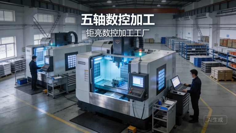
Sheet metal CNC costs rise when a job moves between vendors. Cutting at one shop, bending at another and finishing at a third adds freight, handling, re-inspection and a tolerance stack nobody owns. A supplier that runs cutting, forming, machining and finishing under one roof can hold one tolerance chain and one inspection record. GreatLight runs 127 high-precision CNC machines across three plants in Dongguan and Singapore, with sheet metal fabrication, 5-axis machining and surface finishing in the same quality system.
Ask about the process chain before you ask about the price. Who cuts the blank, who forms it, who deburrs and who does final inspection? If the answer involves more than one company, add the handoff risk to your comparison. Certifications matter here too: ISO 9001:2015 covers general work, while IATF 16949:2016 and ISO 13485:2016 add traceability and validation steps that automotive and medical programs require.
Tolerance strategy is the last lever. A drawing that calls ±0.005 mm on every dimension forces the shop to machine, not just form. Reserve that tolerance for mating holes, bearing seats and connector cutouts. Sheet metal features like overall length, bend-to-bend distance and hole position for clearance can run at ±0.1 mm to ±0.25 mm with no functional loss.
Productionize the part for the process that will actually run it. A prototype made on a laser and a press brake may need a different flat pattern than a production part run on a turret punch. Sending the prototype flat pattern straight to production tooling is a common and expensive mistake. Ask the shop to review the flat pattern before committing.
- 1One roof, one tolerance chainCutting, forming, machining and finishing in one quality system.
- 2Match cert to marketIATF 16949 for automotive, ISO 13485 for medical programs.
- 3Tolerance where it counts±0.005 mm on mating features, ±0.1–0.25 mm elsewhere.
Seven steps to take before the next quote
Work through them in order; each step feeds the next.
- 1Run a DFM check on the modelVerify inside bend radius at 1× thickness for steel and aluminum, 1.5–2× for 304/316. Move holes to at least 2.5× thickness plus bend radius from any bend line. Widen slots below 1× thickness.
- 2Re-derive the material and gaugeWrite down the load, the environment and the finish process. Then pick the thinnest gauge that passes all three. Confirm whether the gauge callout follows the steel or aluminum table.
- 3Standardize thicknesses across the assemblyReduce to one or two gauges per product family. Mixed gauges split the nest and add setups.
- 4Count operations, then merge partsList every routing step. Merge left and right parts that differ by one feature, and replace small weldments with a single folded part where the brake capacity allows.
- 5Remove or form the hardwareReplace tapped holes in sheet under 1.5 mm with extruded threads or clinch fasteners. Keep purchased hardware only where service access or thread strength requires it.
- 6Right-size the finishSpecify as-machined Ra 1.6–3.2 μm for hidden surfaces. Tighten to Ra 0.8–1.6 μm only on sealing and bearing faces. Keep laser marking at 1.5 mm character height or larger.
- 7Set tolerance by functionApply ±0.005 mm to mating holes and seats. Let overall length and bend-to-bend dimensions run at ±0.1 mm to ±0.25 mm. Have the shop review the flat pattern before production tooling is cut.
Which change pays off first
Ranked by typical impact on sheet metal CNC costs for low-to-mid volume runs.
| Change | When it applies | Typical effect |
|---|---|---|
| Material and gauge review | Part carries a spec from an older revision | Largest single-line reduction |
| Merge parts / cut setups | Assembly has mirrored or near-identical parts | Removes a fixture, program and inspection |
| DFM pass on bend radii | Inside radius under 1× thickness on 304/316 | Avoids scrap and relief cuts |
| Replace weldments | Frame made of five or more small plates | Drops weld, straighten and re-inspect steps |
| Right-size finishing | Finish specified by habit, not function | Removes batch minimum and masking labor |
| Tolerance by function | Every dimension called at ±0.005 mm | Keeps forming instead of machining |
| Single-source process chain | Work split across three vendors | Removes freight and handoff re-inspection |
The cheapest part is the one designed for the process
Material and gauge decisions set the floor on sheet metal CNC costs, and everything after that is execution. Fix the alloy, the thickness and the bend radii first, then cut setups and finishing. If you want a second opinion before releasing the drawing, our engineers return a quotation and a free DFM analysis within 12 hours.
Questions engineers ask next
How much does a bend radius change the price?
A radius below 1× material thickness on 304 or 316 stainless usually forces a relief cut or a stress-relief step, and it raises the scrap rate on the outside of the bend. Moving from 0.5 mm to 0.8 mm inside radius on 1.5 mm stainless often keeps the part inside its functional spec while removing that extra operation.
The safe range depends on alloy. Mild steel and aluminum handle 1× thickness. Stainless wants 1.5× to 2×. Check the outside surface after forming; orange peeling means the radius is too tight for the temper.
Is laser cutting always cheaper than CNC punching?
It depends on quantity and geometry. Laser wins on low volume, thick plate and complex contours because there is no tooling cost. Turret punching wins above a few thousand parts when the geometry repeats, because the cycle time per hit is short and the tooling is amortized.
Mixed nests are common. Many shops punch the repetitive holes and laser the outer profile and cutouts in the same program.
What tolerance can sheet metal actually hold?
Formed features are not the same as machined features. Bend-to-bend dimensions typically hold ±0.1 mm to ±0.25 mm depending on part size and thickness. Hole position for clearance can hold ±0.1 mm.
If a dimension must hold ±0.005 mm, plan for a machining operation after forming. That is normal on mating faces and bearing seats, and it should be called out as a machined feature on the drawing.
Does a lower gauge always reduce cost?
No. Thinner material saves on raw stock but can force extra support ribs, more fasteners or a heavier finish to meet stiffness. It also bends differently, which may change the flat pattern.
Compare total cost, not material cost. A 1.5 mm part with two formed ribs can be cheaper than a 3 mm flat part and stiffer at the same time.
Can I skip finishing entirely for a prototype?
Yes, if the part is not visible, not handled regularly and not exposed to moisture. As-machined or as-cut surfaces at Ra 1.6–3.2 μm are fine for fit checks and functional testing.
Add finishing before any corrosion, wear or cosmetic test. Powder coating and anodizing change dimensions slightly, so the flat pattern and hole sizes may need to account for coating thickness.
How do I compare quotes from different suppliers fairly?
Ask each supplier to break the quote into material, cutting, forming, secondary operations, finishing and inspection. Then compare the operation list, not the total. A lower total often hides an extra handoff or a looser inspection plan.
Also confirm the tolerance chain and the certification that applies to your market. IATF 16949:2016 and ISO 13485:2016 add validation steps that change the price for a reason.
Send the drawing, get a DFM report back
Upload the model and we will mark the bend radii, gauge choices and secondary operations that are driving cost. No minimum order quantity, from one prototype to 10,000+ part runs.
12-hour quote + DFMNo minimum order quantity100% inspection before shipmentNDA on request
More process notes from the shop floor
We publish setup notes, tooling trials and inspection data from the factory floor.











