
CNC Machine Tolerance: What a Shop Can Actually Hold
A working engineer's answer to the tolerance question, written for people who have to put a number on a drawing and defend it. We cover real production limits, where they come from, and when a tighter callout costs you money without buying function.
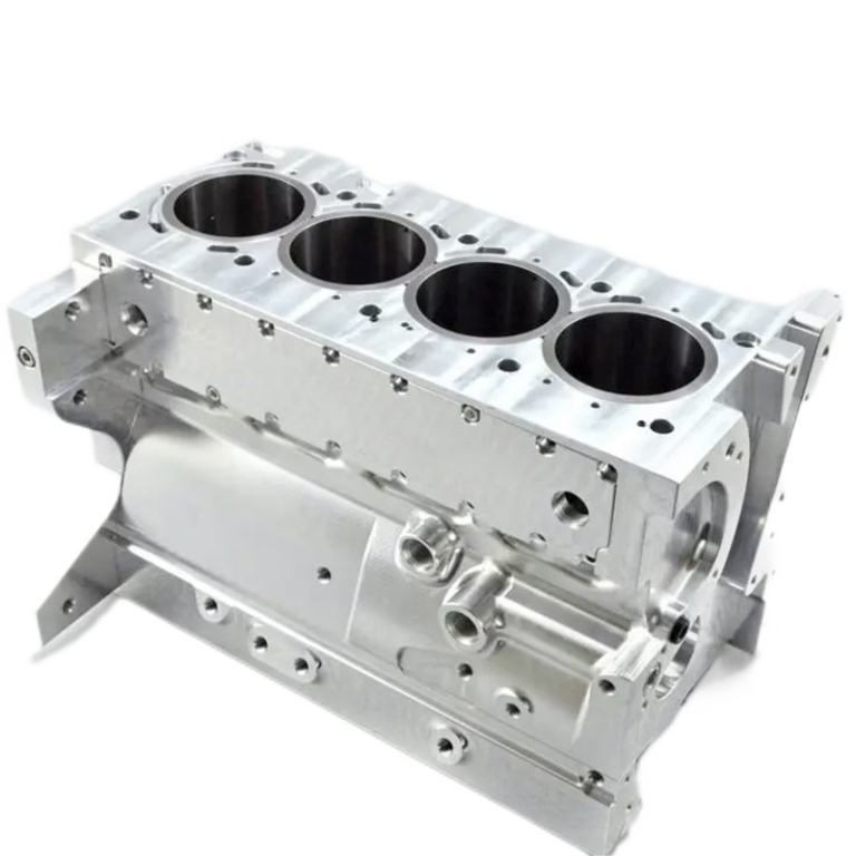
What CNC machine tolerance actually measures
Tolerance is the allowed spread on a dimension. A 25 mm bore drawn at ±0.05 mm may land anywhere from 24.95 to 25.05 mm and still pass. The number says nothing about the machine alone. It describes a system: spindle, tool, fixture, material, thermal state, and the person deciding when to stop cutting.
So the honest answer is a range, not a single figure. In our shop, ±0.005 mm (±0.0002 in) is the working production tolerance on critical features in metals, checked at 20 °C. That is a repeatable number across a run, not a lucky single part.
Two more numbers matter as much as the dimensional one. Surface finish and geometric tolerance decide whether a part assembles and seals. A shaft can sit dead-center on diameter and still fail if it is bowed 0.03 mm over 200 mm.
When you write a tolerance, you are really writing a test plan. Ask what instrument will check it, at what temperature, and how often. If nobody can answer that, the callout is decoration.
- 1DimensionalDiameter, length, slot width. Measured with a micrometer or CMM.
- 2GeometricFlatness, concentricity, position. Measured against datums.
- 3SurfaceRa in μm. Affects friction, sealing, and fatigue life.
Where the practical limits come from
A three-axis mill with a 40-taper spindle and a vise can hold ±0.025 mm all day. Push toward ±0.010 mm and you start fighting thermal drift, tool push-off, and chip evacuation. The machine is not suddenly inaccurate. The error budget just gets used up faster.
Five-axis simultaneous machining changes the picture. On our 16 simultaneous 5-axis centers, we cut contoured features in one setup, so stacked datums disappear. That removes one of the largest error sources: re-fixturing a part four times and adding four locating errors.
Spindle speed and tool runout set the floor for surface finish. A balanced holder at 12,000 rpm with 0.005 mm runout gives a predictable Ra. The same tool in a worn holder at 0.03 mm runout will chatter and smear, and no amount of feed adjustment fixes it.
Machine geometry also limits size. Our largest travel is 4,000 × 400 × 150 mm. A 3,000 mm rail can be milled in one pass, but holding ±0.01 mm over that length requires temperature control and a warm-up cycle before the first cut.
- 13-axis±0.025 mm typical, ±0.010 mm with care
- 24-axisAdds rotary positioning to ±0.01 mm on indexed faces
- 35-axisContoured features in one setup, fewer datum stacks
Seven factors that eat your tolerance
Thermal expansion is the biggest silent killer. Aluminum grows about 23 μm per meter per °C. A 500 mm part that warms 5 °C during roughing moves 0.0575 mm before finishing starts. That is why we rough, cool, then finish.
Tool deflection scales with stick-out cubed. A 6 mm end mill hanging 40 mm out of the holder bends far more than the same tool at 20 mm. For tight slots, use the shortest tool that reaches, and take lighter radial cuts.
Fixture rigidity decides whether the part moves. Thin walls and unsupported bosses deflect under clamping force and spring back after unclamping. Soft jaws machined to the part profile fix most of this.
Material behavior matters too. 6061-T6 machines cleanly and holds ±0.005 mm well. 316L stainless work-hardens, pulls tools, and needs slower speeds. Inconel and Ti-6Al-4V move more after cutting because residual stress releases.
Tool wear drifts dimensions across a run. On a 500-piece order, the tenth part and the five-hundredth part come off different tool edges. In-process probing or scheduled offsets keep the spread tight.
Machine condition is the last item but not the least. A spindle with 0.002 mm runout cannot produce a ±0.005 mm bore reliably, no matter what the control says.
Finally, the programmer sets the outcome. Conservative speeds and a spring pass cost seconds. Chasing a scrap bin costs hours.
- 1ThermalRough, cool, finish. Measure at 20 °C.
- 2DeflectionShort tools, light radial engagement, rigid fixtures
- 3WearProbe or offset every 20–50 parts on long runs
How to set a tolerance that buys function, not ego
Start from the fit, not the machine. If a bearing sits in a housing, look up the recommended fit for that bearing size and load. That number comes from the bearing maker, not from what feels precise.
Tolerance only the features that touch something. A mounting face, a bore, a locating pin hole. Free surfaces, clearance holes, and cosmetic edges can carry ±0.1 mm or a general title-block tolerance. This one habit cuts cost more than any other.
Watch stacked tolerances. Four parts in an assembly, each at ±0.05 mm, can put the last feature 0.2 mm off nominal. Sometimes the right fix is a tighter single datum feature and looser everything else, not four tight parts.
Ask about the inspection plan before you freeze the drawing. If a ±0.005 mm callout needs a CMM with a temperature-controlled room, that is fine. It just belongs in the quote conversation, not in a surprise email after delivery.
Also decide early whether the tolerance applies to the finished part or the as-machined part. Anodizing adds 5–25 μm per surface. A hardcoat can add more. Plating and coating change dimensions after the last cut.
- 1Tight only where it touchesFit surfaces tight, everything else general
- 2Check the stackSum the tolerances before you tighten one part
- 3Finish firstAccount for coating thickness in the drawing
How we hit tight tolerance on a real job
A rough sequence for a part with ±0.005 mm critical features.
- 1Review the drawing for functionMark which features mate, seal, or locate. Flag any tolerance that no instrument can verify.
- 2Free DFM feedbackQuotation and DFM analysis within 12 hours, with notes on features that will fight the tolerance.
- 3Choose the setup countOne 5-axis setup beats four 3-axis setups. Fewer datums, less stack-up.
- 4Rough and stress-relieveLeave 0.3–0.5 mm stock, let the part cool, relieve stress if the material calls for it.
- 5Finish at controlled temperatureCut finishing passes with the shop at 20 °C and the part soaked to match.
- 6Inspect and record100% inspection before shipment, with reports on request.
Typical tolerance by process and feature
Numbers reflect our production capability, not a guarantee for every geometry.
| Feature | Typical hold | Tighter limit | Notes |
|---|---|---|---|
| Milled pocket, 3-axis | ±0.025 mm | ±0.010 mm | Depends on depth-to-width ratio |
| Bored hole, 5-axis | ±0.010 mm | ±0.005 mm | Reamed or bored, not drilled |
| Turned OD, mill-turn | ±0.010 mm | ±0.005 mm | Steady rest for long shafts |
| Slot width | ±0.020 mm | ±0.008 mm | Shortest tool, light radial cut |
| Hole position | ±0.025 mm | ±0.010 mm | One setup beats four |
| Flatness, 200 mm | 0.020 mm | 0.008 mm | Face mill, cool part |
| Surface finish | Ra 1.6–3.2 μm | Ra 0.2–0.8 μm | As-machined to fine finish |
| Max part size | 4,000 mm | – | Travel 4,000 × 400 × 150 mm |
The verdict on tolerance
If the feature mates, seal, or carries load, spend the money on ±0.005 mm and one good setup. If it is clearance or cosmetic, put a general tolerance on the title block and let the shop run faster. Tightening a free surface buys nothing and costs everywhere.
Questions engineers ask next
What is the tightest tolerance a CNC machine can hold?
For production runs, ±0.005 mm (±0.0002 in) on critical metal features is a realistic working limit when the part is small, rigid, and measured at 20 °C.
Single features on a warm machine can go tighter. The problem is repeating it on part 200 without extra inspection and slower cutting.
Does a tighter tolerance always cost more?
Usually yes, but not in a straight line. The jump from ±0.05 mm to ±0.025 mm is mostly process discipline. The jump from ±0.010 mm to ±0.005 mm adds temperature control, probing, and slower feeds.
The bigger cost driver is often the inspection, not the cutting.
How does material choice affect tolerance?
Aluminum 6061-T6 holds tight dimensions with little post-cut movement. Stainless 316L work-hardens and pushes tools, so dimensions drift faster.
Titanium and Inconel release residual stress after cutting and can move 0.02–0.05 mm on a thin section. Plan a stress-relief step or leave more stock.
Can 5-axis machining improve tolerance?
It improves position tolerance more than size tolerance. Cutting five faces in one setup removes re-fixturing errors, which are often the largest single error source.
Size tolerance still depends on tool, spindle, and thermal control.
How do I know the tolerance was met?
Ask for the inspection method and the report. We inspect 100% before shipment and can supply dimensional reports on request.
If a callout needs a CMM, say so at the quote stage so the inspection time is in the price.
What about surface finish alongside tolerance?
They are separate callouts. We hold Ra 1.6–3.2 μm as-machined, Ra 0.8–1.6 μm on high-finish features, and Ra 0.2–0.8 μm with fine finishing.
A tight finish on a tight dimension usually means a separate finishing pass with a fresh tool.
Send us the drawing, get a tolerance answer
Upload your part and we will return a quote plus free DFM analysis within 12 hours, with notes on which callouts are buildable as drawn.
12-hour quote100% inspectionNo minimum order quantityNDA on request
More from the shop floor
We publish setup notes, tooling trials and inspection data from the factory floor.











